Small-sized hydroelectric generator

a hydroelectric generator and small technology, applied in the direction of liquid fuel engines, renewable energy generation, greenhouse gas reduction, etc., can solve the problems of impeller and shaft bearing which supports the medial axis of rotation of the rotator, and achieve the effect of constant and stable output voltag

Inactive Publication Date: 2005-06-16
TAIYO KAGAKU CO LTD
View PDF3 Cites 9 Cited by
  • Summary
  • Abstract
  • Description
  • Claims
  • Application Information

AI Technical Summary

Benefits of technology

[0007] This invention is made in view of the above-mentioned problems, and the purpose of the invention is to provide a small-sized hydroelectric generator for obtaining a constant and stable output voltage even when a quantity of water flow is large or when a water pressure is high.
[0008] To achieve the above-mentioned purpose, the small-sized hydroelectric generator of this invention comprises a casing having an inflow port at one end and an outflow port at the other end, a rotator rotated integrally with an impeller and a stator for generating electricity by the rotation of the rotator arranged in the casing. A main passage which goes from the inflow port to the outflow port through a center part of the rotator, and a bypass which goes from the inflow port to the outflow port detouring around an outer peripheral side of the stator are provided as passages for water flow going from the inflow port to the outflow port. Inside the bypass, a check valve is arranged which is urged by a spring in a direction of stopping the water flow coming from the inflow port.
[0009] In the small-sized hydroelectric generator structured as mentioned above, a partition wall is arranged between the inflow port and the impeller to form a space as a water flow chamber between the inflow port and the partition wall. A first jet orifice is formed in a state that it opens toward the impeller from a part of the outer periphery of the water flow chamber through the outer peripheral part of the partition wall. The water flow chamber is made to communicate with the bypass. A second jet orifice is formed in a state that it opens toward the impeller from the passage section before reaching the check valve in the bypass penetrating the outer peripheral part of the partition wall.
[0010] The small-sized hydroelectric generator according to this invention comprises a casing having an inflow port at one end, an outflow port at the other end, a rotator rotated integrally with an impeller and a stator for generating electricity by the rotation of the rotator, which rotator and the impeller are arranged in the casing. In the small-sized hydraulic generator, a main passage which goes from the inflow port to the outflow port through a center part of the rotat

Problems solved by technology

However, according to the conventional small-sized hydroelectric generator as mentioned above, since a whole quantity of water flowing inside the water pipe is applied to the impeller for use as a rotational energy for the rotator, the output voltage from the stator increases in proportion to the quantity of water flow, as shown in FIG. 4, whereby not only a consta

Method used


Image

  • Small-sized hydroelectric generator
  • Small-sized hydroelectric generator
  • Small-sized hydroelectric generator

Examples


Embodiment Construction

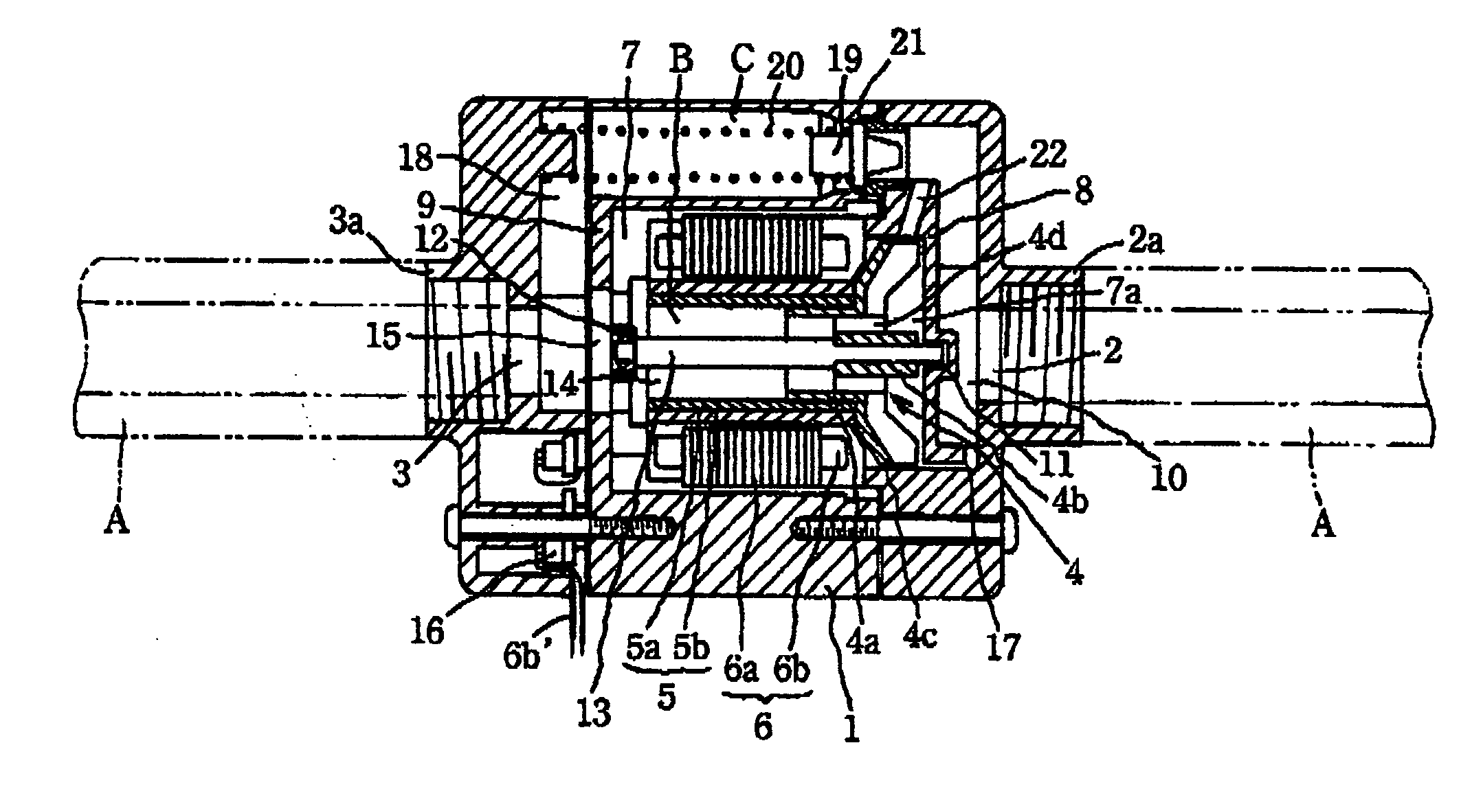
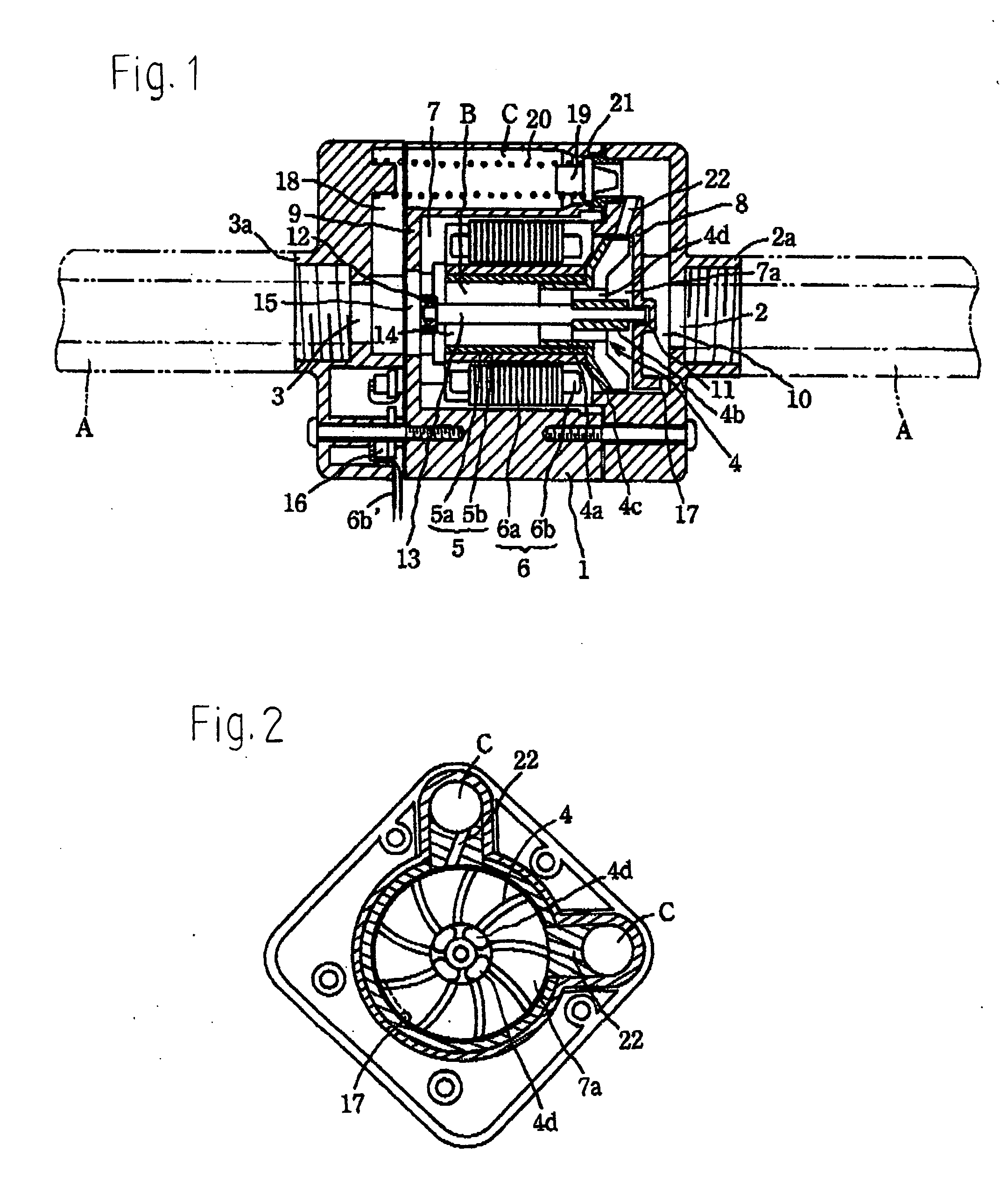
[0020] Now, the specific embodiment of the invention is explained hereinafter based on the drawings. A casing 1, being a main body of the small-sized hydroelectric generator, is a hollow casing. An inflow port 2 and an outflow port 3 for tap water are formed in a center of one end and in a center of the other end of the casing 1, respectively, and a rotator 5 rotating integrally with an impeller 4, and a stator 6 generating electricity by the rotation of the rotator 5, are arranged in the center part of the inside of the casing 1.

[0021] The inflow port 2 and the outflow port 3 are formed to have inner diameters substantially same as an inner diameter of a water pipe A. Short cylindrical connection opening parts 2a, 3a, having diameters larger than those of the inflow port 2 and the outflow port 3, respectively, are mounted to project from circumferences of the inflow port 2 and the outflow port 3, respectively. By screwing an outer peripheral surface of the end parts of the water p...


PUM


Abstract

A rotator with an impeller and a stator generating an induced voltage are arranged in a casing. The tap water flowing flows through a main passage, which has a first jet orifice facing the impeller, and rotates the impeller. A bypass running from the inflow port and passing around an outer periphery of the stator is provided. When the water pressure is high, a check valve closing the bypass is opened against a spring force and the water flows out to a drain port, while the impeller is stably rotated by a pressure of water jetted from a second jet orifice penetrating from the bypass to face the impeller, which pressure is in reverse proportion to a speed of flow inside the bypass.

Description

BACKGROUND OF THE INVENTION [0001] 1. Field of the Invention [0002] This invention relates to a small-sized hydroelectric generator for generating electricity by utilizing the water flow that runs inside a water pipe. [0003] 2. Description of the Prior Art [0004] A conventional small-sized hydroelectric generator is known, in which electricity is generated by utilizing water flowing inside a water pipe for use as a source of electricity for controlling a valve of automatic hand washer or the other devices, or as a source of electricity for products using a dry battery, for example, by charging up a condenser or an accumulator. [0005] A structure of the conventional small-sized hydroelectric generator is as follows. Namely, an inflow port connecting and communicating with the water pipe is formed at an end of a casing and an outflow port is formed on the other end thereof. An electricity generating section comprising a stator and a rotator is arranged inside the casing. An impeller i...

Claims


Application Information

Patent Timeline
IPC IPC(8): F01D11/00H02K7/08F03B13/00H02K7/18
CPCF03B13/00Y02E10/28Y02E10/223F05B2220/20F05B2250/82Y02E10/20
Inventor MOTONAKA, HIROSHISHIOZAKI, YOSHIO
Owner TAIYO KAGAKU CO LTD
Why Eureka
Try Eureka