
Nanostructure augmentation of surfaces for enhanced thermal transfer with increased surface area

a technology of nanostructure and enhanced thermal transfer, applied in the field of thermal management, can solve the problems of device failure, limitations of conventional thermal management technology, which has been effective for many years, etc., and achieve the effect of improving thermal contact and increasing the surface area for convective heat transfer

Inactive Publication Date: 2005-06-16
CHOPRA NASREEN
View PDF8 Cites 43 Cited by
  • Summary
  • Abstract
  • Description
  • Claims
  • Application Information

AI Technical Summary

Benefits of technology

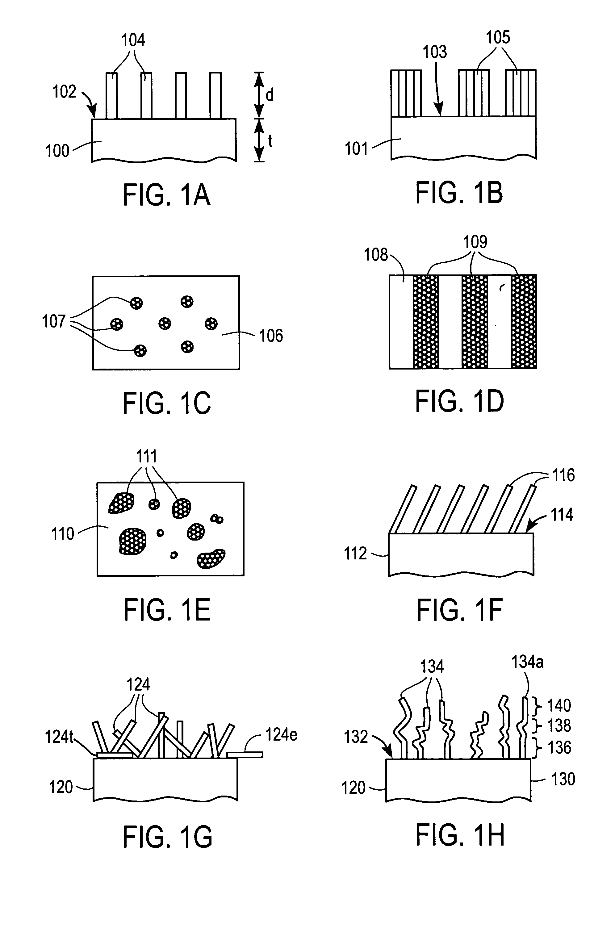
[0025] Embodiments of the present invention provide nanostructure augmentation of surfaces of thermally active devices (i.e., any device that generates, dissipates, collects or otherwise transfers heat to or from any other device or fluid medium). In some embodiments, increased surface area for convective heat transfer is obtained by sparsely coating a surface with nanostructures such as nanotubes or bundles of nanotubes so that air or other cooling fluid can flow between the nanotubes or bundles. In other embodiments, improved thermal contact is obtained by densely coating a surface with nanotubes or bundles of nanotubes.
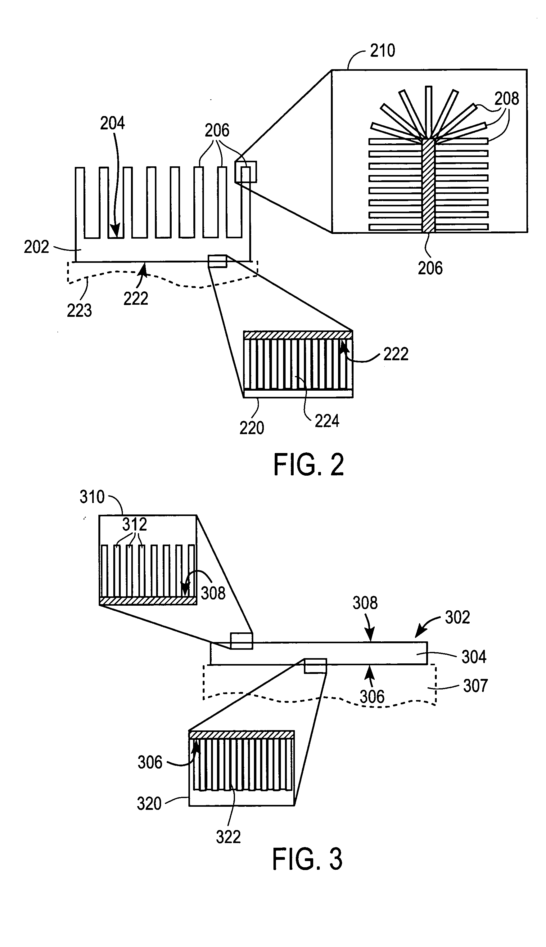
[0029] According to still another aspect of the present invention, a package for a heat generating device includes a housing adapted to enclose the heat generating device, where the housing has an inner surface and an outer surface, and first nanostructures disposed on at least a portion of the outer surface, at least some of the nanostructures being spaced from others of the nanostructures by a distance sufficient to permit flow of a cooling fluid therebetween. The heat generating device may include an integrated circuit or any other type of heat generating device. Additionally, second nanostructures may be disposed on at least a portion of the inner surface of the housing, and the second nanostructures may be arranged so as to enhance thermal transfer between the housing and the heat generating device.

Problems solved by technology

Electronic devices such as microprocessors or other integrated circuits devices generate heat as they operate, and excessive heat can lead to device failure.
This conventional thermal management technology, which has been effective for many years, has its limitations.

Method used


Image

  • Nanostructure augmentation of surfaces for enhanced thermal transfer with increased surface area
  • Nanostructure augmentation of surfaces for enhanced thermal transfer with increased surface area
  • Nanostructure augmentation of surfaces for enhanced thermal transfer with increased surface area

Examples


Embodiment Construction

Overview and Terminology

[0040] Embodiments of the present invention provide nanostructures that can improve thermal transfer into or out of an object. The term “nanostructure,” or nanoscale structure, as used herein denotes a structure with at least one dimension that is on the order of nanometers (e.g., from about 1 to 100 nm); one or more of the other dimensions may be larger and may be microscopic (from about 10 nm to a few hundred micrometers) or macroscopic (larger than a few hundred micrometers). The nanostructures can be applied to the surface of any device into or out of which heat is to be transferred, including heat sinks, packaging materials for semiconductor devices, and a wide variety of other devices. In some embodiments, the nanostructures are arranged so as to increase the area of a heat-exchanging surface without increasing the footprint; such arrangements can promote convective heat transfer between the object and a fluid medium to which the heat-exchanging surfa...


PUM

PropertyMeasurementUnit
distancesaaaaaaaaaa
distancesaaaaaaaaaa
distanceaaaaaaaaaa

Abstract

Nanostructures provide increased surface area to augment heat-exchange surfaces of various devices or structures. In one embodiment, an article of manufacture has a body having a heat-exchanging surface and nanostructures disposed on the heat-exchanging surface. The nanostructures are arranged to enhance thermal transfer between the body and a region of fluid and may be spaced apart from each other to permit flow of a fluid between the nanostructures. Examples of suitable nanostructures include carbon and / or boron nitride nanotubes, which may be grown on the heat-exchanging surface.

Description

CROSS-REFERENCES TO RELATED APPLICATIONS [0001] This application claims the benefit of the following six provisional U.S. patent applications: [0002] Application No. 60 / 503,591, filed Sep. 16, 2003, entitled “Nano-Material for System Thermal Management”; [0003] Application No. 60 / 503,612, filed Sep. 16, 2003, entitled “Oriented Nano-Material for System Thermal Management”; [0004] Application No. 60 / 503,613, Sep. 16, 2003, entitled “Nano-Material Thermal and Electrical Contact System”; [0005] Application No. 60 / 532,244, filed Dec. 23, 2003, entitled “Nanotube Augmentation of Heat Exchange Structure”; [0006] Application No. 60 / 544,709, filed Feb. 13, 2004, entitled “Nano-Material Thermal Management System”; and [0007] Application No. 60 / 560,180, filed Apr. 6, 2004, entitled “Heat Transfer Structure.”[0008] This application incorporates by reference for all purposes the entire disclosures of the following seven provisional U.S. patent applications: [0009] Application No. 60 / 503,591, fi...

Claims


Application Information

Patent Timeline
Patent Type & Authority Applications(United States)
IPC IPC(8): B32B5/16
CPCY10T428/25B82Y30/00B32B5/16
Inventor LEE, JU-HYUNGCHOPRA, NASREEN G.
Owner CHOPRA NASREEN
Learn More