No-vent liquid hydrogen storage and delivery system

Inactive Publication Date: 2005-06-23
SIERRA LOBO
View PDF18 Cites 9 Cited by
  • Summary
  • Abstract
  • Description
  • Claims
  • Application Information

AI Technical Summary

Problems solved by technology

Furthermore, hydrogen fuel is abundantly available in limitless supply, whereas existing fossil fuel reserves are finite, and eventually will run out.
However, widespread use of hydrogen as automobile fuel has been prevented due to several major concerns.
In particular, storing and handling liquid hydrogen is difficult and can be dangerous.
Hydrogen is highly combustible and is prone to explode when combined with atmospheric oxygen in the presence of an ignition source.
Neither of these hydrogen storage mechanisms is suitable for use in privately owned and operated automobiles.
The size of these tanks is further limited due to space and weight constraints in an automobile.
The limited storage volume for hydrogen fuel means limited automobile driving range between refuelings.
Another perhaps more significant disadvantage is that storing a highly explosive fuel, such as gaseous hydrogen, at high pressure on the order of 5000 psia in an automobile presents a significant danger to both occupants and bystanders should the pressure tank or associated high pressure hardware fail.
Second, conventional low pressure liquid hydrogen storage vessels are unsuitable for storing hydrogen fuel in automobiles due to the requirement of venting vaporized hydrogen gas to the atmosphere.
Hydrogen overpressure results from heat transfer from the environment into the storage vessel causing liquid hydrogen to boil and vaporize.
In fact, even if it were possible to provide such stationary hydrogen vent stacks, automobiles are by definition “mobile,” and it is totally impractical to limit people to stationing their cars only in locations where there is an available hydrogen vent stack.
In addition, the near continuous ventin

Method used


Image

  • No-vent liquid hydrogen storage and delivery system
  • No-vent liquid hydrogen storage and delivery system
  • No-vent liquid hydrogen storage and delivery system

Examples


Embodiment Construction

[0021] As used herein, when a range such as 5 to 25 (or 5-25) is given, this means preferably at least 5, and separately independently, preferably not more than 25. Unless otherwise specified, all components described herein are made from conventional materials in a conventional manner.

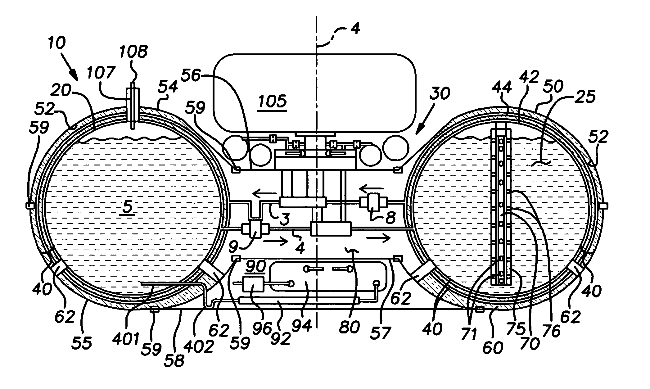
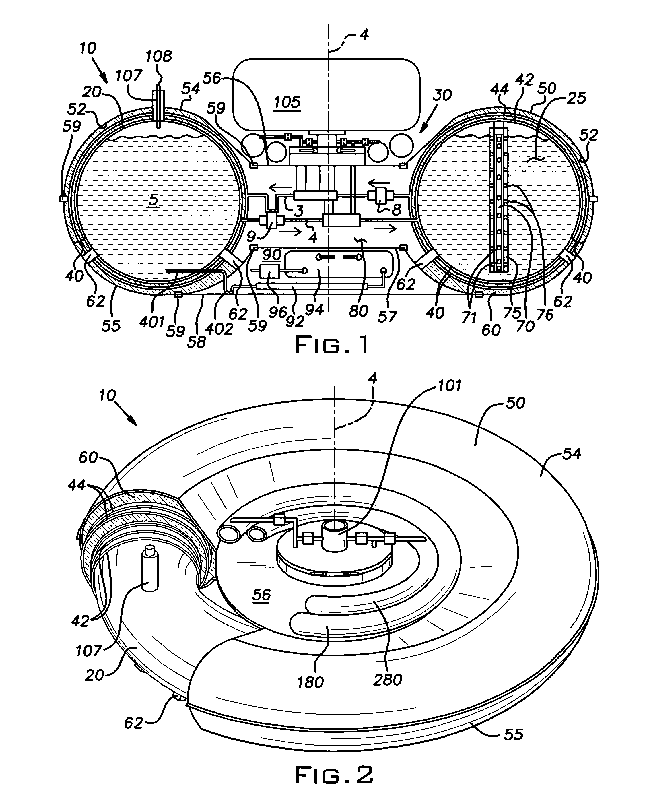
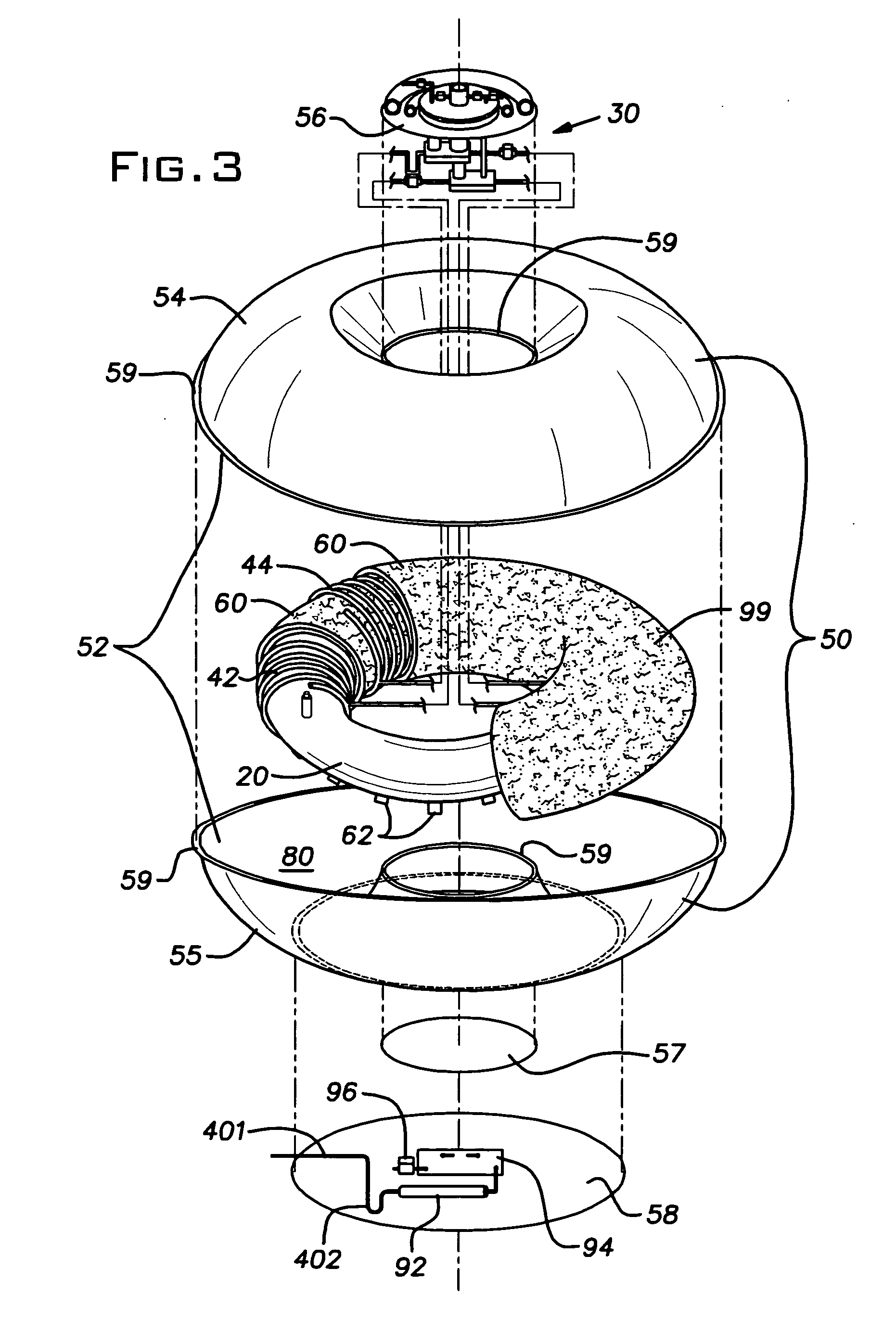
[0022] A liquid hydrogen storage and delivery system 10 is provided that is cooled via an orifice pulse tube refrigerator. In its broadest aspect, the invention includes a liquid hydrogen storage vessel 20, an orifice pulse tube refrigerator (OPTR) 30, and a cooling system 40 coupled to the OPTR 30 and adapted to cool the storage vessel 20, or to shield it from ambient thermal energy. In the preferred embodiment, the OPTR 30 has two cooling or refrigeration stages as more fully described below. The storage and delivery system 10 is suitable to be provided or incorporated into an automobile equipped with a hydrogen powered internal combustion engine, and / or a hydrogen powered fuel cell, to store liqui...


PUM


Abstract

A hydrogen storage and delivery system is provided having an orifice pulse tube refrigerator and a liquid hydrogen storage vessel. A cooling system, coupled to the orifice pulse tube refrigerator, cools the vessel and abates ambient heat transfer thereto in order to maintain the liquid hydrogen in the vessel at or below its saturation temperature. Hydrogen boil-off, and the necessity to provide continuous venting of vaporized hydrogen are minimized or avoided. In a preferred embodiment, the hydrogen storage vessel has a toroidal shape, and the pulse tube refrigerator is a two stage pulse tube refrigerator and extends within a central void space defined at the geometric center of the toroidal storage vessel. Also in a preferred embodiment, the cooling system includes first and second thermal jackets, each having a substantially toroidal shape and enclosing the storage vessel, wherein each of the thermal jackets is thermally coupled to one of the first or second stages of the pulse tube refrigerator in order to cool the vessel and to abate ambient heat leak thereto. The hydrogen storage and delivery system is particularly suitable for use in vehicles, such as passenger automobiles.

Description

[0001] This application claims the benefit of U.S. Provisional Patent Application Ser. No. 60 / 461,639 filed Apr. 9, 2003, the contents of which are incorporated herein by reference.BACKGROUND OF THE INVENTION [0002] 1. Field of the Invention [0003] The present invention relates to a system for storing and dispensing liquid hydrogen without venting, and more particularly to such a storage and delivery system for use in an automobile, light or heavy duty trucks, boats, or transportation systems or vehicles in general that use hydrogen for fuel, such that a vehicle can store a large quantity of hydrogen fuel in the liquid state without requiring hydrogen venting due to boil-off. [0004] 2. Description of Related Art [0005] Recently, and especially in view of the global oil climate, the automotive industry has reported serious development efforts to produce hydrogen powered vehicles. A key benefit to using hydrogen as opposed to conventional fossil fuels is that hydrogen burns cleanly, p...

Claims


Application Information

Patent Timeline
IPC IPC(8): B60KF17C1/00F17C5/02F25B9/00F25J1/00H01M8/04
CPCF17C1/00F17C2270/0178F25B9/145F25B2309/1408F25B2309/1413F25B2309/1415F25B2309/14241F25D19/006Y02E60/321F17C2201/0133F17C2201/032F17C2201/056F17C2201/058F17C2205/0111F17C2221/012F17C2223/0161F17C2223/033F17C2227/0341F17C2227/0386F17C2260/033F17C2270/0168F17C2270/0171F25B9/10Y02E60/32
Inventor HABERBUSCH, MARK S.PARKES, JAMESCULLER, ADAM JOHN
Owner SIERRA LOBO
Why Eureka
Try Eureka