
Boring tool tracking fundamentally based on drill string length, pitch and roll

a drilling tool and drill string technology, applied in the direction of borehole/well accessories, directional drilling, survey, etc., can solve the problems of affecting the accuracy of the prediction position of the second position, the difficulty of determining the orientation parameter of the yaw in the context of prior art techniques, and the prone to significant measurement error of the direct measurement of the yaw using a magnetometer in the boring tool, etc., to achieve the prediction of the overall orientation and the predicted position accurately character

Inactive Publication Date: 2005-06-23
MERLIN TECH INC
View PDF14 Cites 4 Cited by
  • Summary
  • Abstract
  • Description
  • Claims
  • Application Information

AI Technical Summary

Benefits of technology

The patent describes a system for tracking and guiding an underground boring tool in an underground region. The system uses electromagnetic signals to determine the position of the boring tool. The system includes a boring tool that is steerable underground using a roll orientation. The boring tool can be advanced using a drill string that exhibits a maximum drill string curvature in the region. The system uses a combination of the pitch and roll orientation of the boring tool to determine its overall orientation. The system can track the boring tool over a path segment by measuring the pitch and roll orientation of the boring tool and using extrapolation to determine the predicted position of the boring tool at the end of the path segment. The system can also use the measured yaw orientation of the boring tool to further improve the accuracy of the boring tool's position. Overall, the system allows for precise tracking and guidance of the boring tool in underground regions.

Problems solved by technology

The yaw orientation parameter, however, is considerably more difficult to determine in the context of prior art techniques, as will be discussed below.
Moreover, direct measurement of yaw using, for example, a magnetometer in the boring tool is more problematic than direct measurement of pitch and roll orientation which can be performed with relatively simple mechanical type sensors or based on accelerometers readings.
A particular problem resides in such direct yaw measurements being prone to significant levels of measurement error in the presence of magnetic interference.

Method used


Image

  • Boring tool tracking fundamentally based on drill string length, pitch and roll
  • Boring tool tracking fundamentally based on drill string length, pitch and roll
  • Boring tool tracking fundamentally based on drill string length, pitch and roll

Examples


Embodiment Construction

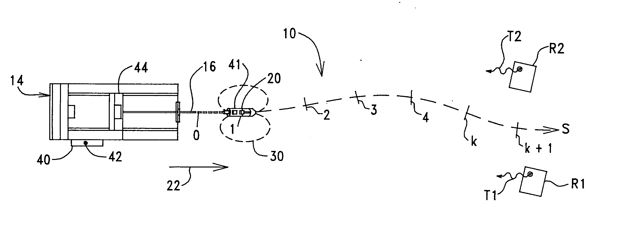
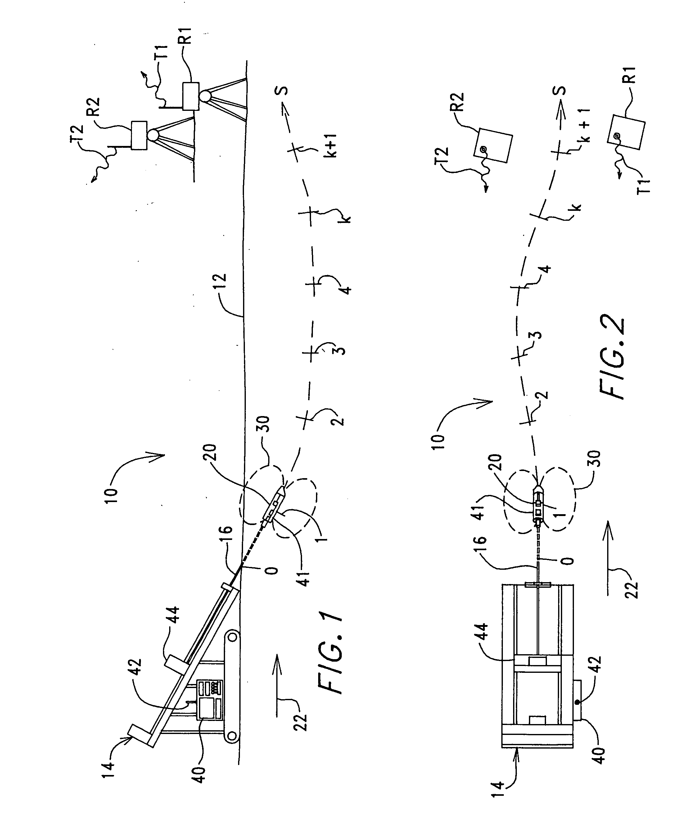
[0033] Turning now to the figures wherein like components are indicated by like reference numbers throughout the various figures, attention is immediately directed to FIG. 1 which diagrammatically illustrates a horizontal directional drilling system generally indicated by the reference number 10 and produced in accordance with the present invention. It is noted that the figures are not to scale for purposes of illustrative clarity and that like reference numbers refer to like components wherever possible throughout the various figures. FIG. 1 is an elevational view of system 10 operating in a region 12. System 10 includes a drill rig 14 having a drill string 16 extending therefrom to a boring tool 20. The drill string is pushed into the ground to move boring tool 20 at least generally in a forward direction 22 indicated by an arrow.

[0034] In the illustrated technique of system 10, a locating signal 30 is transmitted from the boring tool to receivers R1 and R2 positioned on the surf...


PUM


Abstract

A boring tool moves having a pitch orientation, a yaw orientation and a roll orientation and is steerable underground using the roll orientation. A maximum drill string curvature is established for steering. The boring tool is advanced over a path segment. An averaged roll characteristic is determined for movement of the boring tool along the path segment. A path segment pitch orientation is established based on at least one measured pitch orientation along the path segment. Using the maximum drill string curvature in combination with the averaged roll characteristic and the path segment pitch orientation, the yaw orientation is determined. The averaged roll characteristic is determined based on a series of incremental roll measurements that are spaced across the path segment. A set of coupled ordinary differential equations is used to characterize movement of the boring tool.

Description

[0001] This application is a continuation application of copending U.S. patent application Ser. No. 10 / 341,922 filed Jan. 13, 2003, the disclosure of which is incorporated herein by reference.[0002] The present invention relates generally to the field of directional drilling and, more particularly, to a directional drilling system which provides for tracking of a boring tool fundamentally requiring no more than pitch and roll measurements as measured parameters. In one feature, measurement error compensation is accomplished using a Kalman filter within the framework of a heretofore unseen set of coupled ordinary differential equations. BACKGROUND OF THE INVENTION [0003] A boring tool, or other such underground object, is characterized in a drilling region by six unknown parameters comprising a location in three dimensional space, described using some form of coordinates, and orientation parameters that are generally referred to as pitch, roll and yaw. The former two orientation para...

Claims


Application Information

Patent Timeline
Patent Type & Authority Applications(United States)
IPC IPC(8): E21B7/04E21B47/022E21B47/024
CPCE21B7/046E21B47/02224E21B44/00E21B7/04E21B47/024G01V3/081G01V3/38E21B47/0232E21B7/10
Inventor BURROWS, JAMES W.BRUNE, GUENTER W.MERCER, JOHN E.
Owner MERLIN TECH INC
Learn More