Control device for vehicle AC generator

a control device and vehicle ac technology, applied in the direction of electric generator control, dynamo-electric converter control, transportation and packaging, etc., can solve the problems of serious difficulty in designing its algorism, general random on/off timing, etc., and achieve the effect of accurate control and simplified design of its architectur

Inactive Publication Date: 2005-06-23
MITSUBISHI ELECTRIC CORP
View PDF31 Cites 4 Cited by
  • Summary
  • Abstract
  • Description
  • Claims
  • Application Information

AI Technical Summary

Benefits of technology

[0012] In the control device for the vehicle AC generator according to the invention and corresponding to the first object, the flip-flop is used, and the clock pulse with the constant period supplied to this flip-flop repeatedly sets the control period at the constant period and decides the on timing of the power transistor in this control period, and the control pulse supplied to the flip-flop decides the off timing of the power transistor in the control period. Thus, the power transistor is consequently controlled at the constant control period, and the monitor output of the generation rate monitor circuit for monitoring the generation rate in the control period also comes to have the constant period. Accordingly, also in the case where this monitor output is supplied to, for example, an electronic control unit using a microcomputer to perform an engine control, the design of its architecture can be simplified.
[0013] In the control device for the vehicle AC generator according to this invention and corresponding to the second object, the load response control circuit of the voltage control device includes the first and the second control signal circuits, the first control signal circuit performs the load response control for adjusting the generation rate between the lower limit and the upper limit in accordance with the increase in the load, and the second control signal circuit performs, in the case where the load response control is released, the regulated load response control for adjusting the generation rate between the regulated value closer to the upper limit than to the lower limit and the upper limit in accordance with the increase in the load. Accordingly, for example, in the case where the load response control is released, even if the generation rate is temporarily lowered, the regulated load response control is performed subsequently to that. On the basis of the regulated load response control performed subsequently to the temporal lowering of the generation rate, the adjustment of the generation rate continues in plural continuous control periods, so that the generation rate monitor circuit can certainly catch the lowering of the generation rate, and also in the case where the monitor output is supplied to, for example, the electronic control unit using the microcomputer to perform the engine control, a more accurate control can be performed.

Problems solved by technology

However, in the voltage control device of the vehicle AC generator, since the power transistor is turned on and off in accordance with the rectified output voltage, the on / off timing is generally random.
Accordingly, in order to perform a control by the vehicle electronic control unit (ECU) using this, there is serious difficulty in designing its algorism.

Method used


Image

  • Control device for vehicle AC generator
  • Control device for vehicle AC generator
  • Control device for vehicle AC generator

Examples


embodiment 1

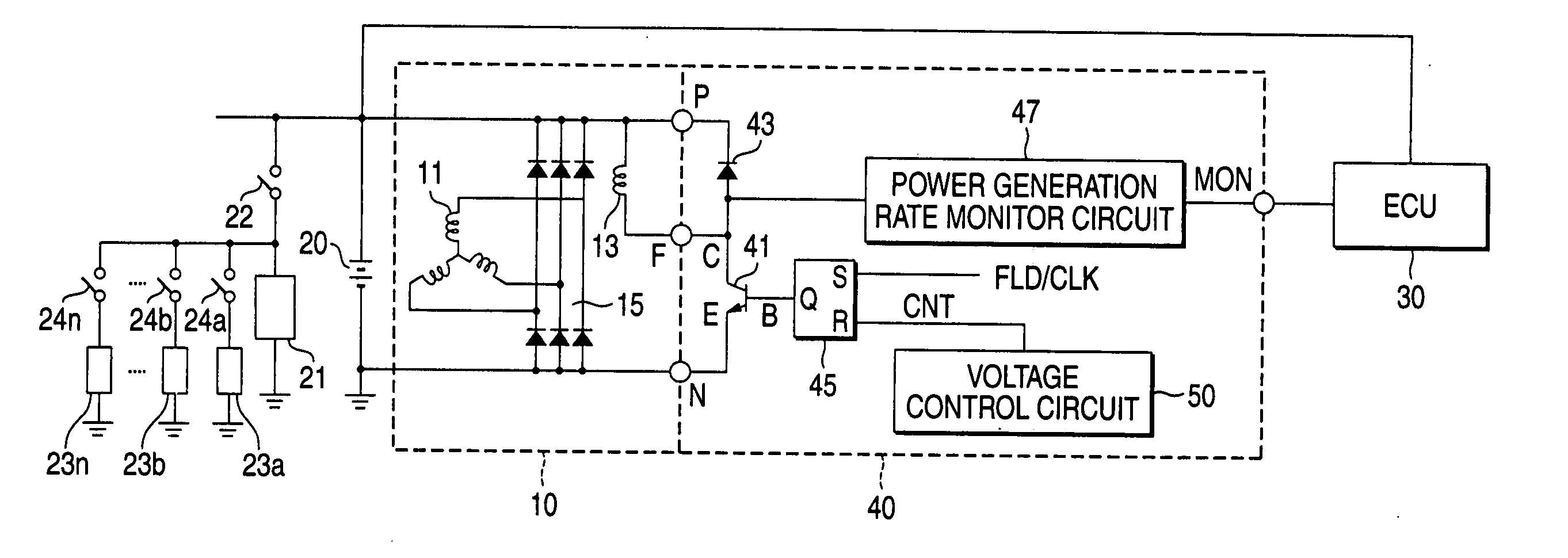
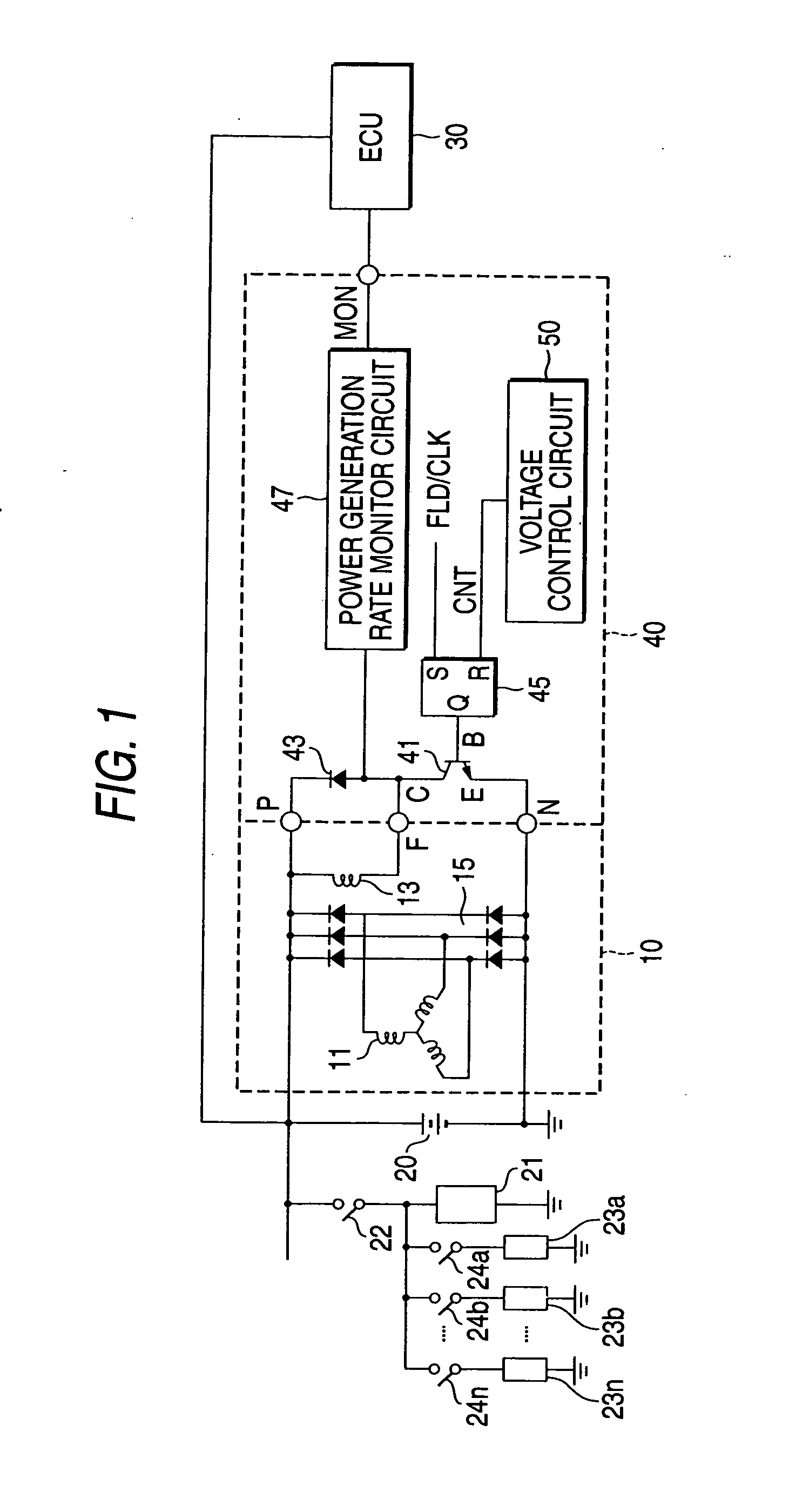
[0022]FIG. 1 is an electric circuit diagram showing embodiment 1 of a control device for a vehicle AC generator according to the invention. This embodiment 1 is the embodiment corresponding to the first object of the invention.

[0023] The control device for the vehicle AC generator shown in FIG. 1 includes an AC generator 10, an on-board battery 20, other vehicle electric loads 21, 23a, 23b, . . . , 23n, a vehicle electronic control unit (ECU) 30, and a voltage control device 40 for the AC generator 10.

[0024] The AC generator 10 includes an armature coil 11, a field coil 13 and a full-wave rectifier circuit 15. This AC generator 10 is constructed such that an armature core around which the armature coil 11 is wound constitutes a rotator, and this rotator is driven by an engine mounted on a vehicle. A field core around which the field coil 13 is wound constitutes a stator and is fixed to the outer periphery of the rotator so as to surround it. The armature coil 11 is a three-phase c...

embodiment 2

[0036]FIG. 4 is an electric circuit diagram showing embodiment 2 of a control device for a vehicle AC generator according to the invention. This embodiment 2 is the embodiment corresponding to the second object, and instead of the voltage control circuit 50 of the embodiment 1, a voltage control circuit 50A in which a load response control LRC is introduced is used, and this embodiment is constructed to improve such disadvantage that especially in the case where this load response control LRC is released, and in the case where the on time ratio TRon of the power transistor 41, that is, the generation rate G of the AC generator 10 is temporarily lowered, it can not be caught by the generation rate monitor circuit 47.

[0037]FIG. 4 shows an inner circuit of the voltage control circuit 50A used in the embodiment 2, together with an SR flip-flop 45. A power transistor 41 of a voltage control device 40, a flywheel diode 43, and a generation rate monitor 47 are the same as those of FIG. 1,...


PUM


Abstract

In a control apparatus of a vehicle AC generator, a flip-flop for receiving a clock pulse with a constant period and a control pulse is used. The clock pulse sets the control period at the constant period, and decides an on timing of the power transistor in this control period. The control pulse decides an off timing. A load response control circuit performs a load response control to adjust an on time ratio of the power transistor from a lower limit to an upper limit in accordance with an increase in load, and a second control signal circuit adjusts the on time ratio from a regulated value close to the upper limit to the upper limit.

Description

BACKGROUND OF THE INVENTION [0001] 1. Field of the Invention [0002] The present invention relates to a control device for a vehicle AC generator which is mounted on a vehicle such as an automobile, charges an on-board battery and feeds other electric loads of the vehicle. [0003] 2. Description of the Related Art [0004] In general, an AC generator is mounted on a vehicle such as an automobile, and by the rectified output of this AC generator, an on-board battery is charged and various electric loads of the vehicle are fed. This vehicle AC generator is driven by an engine, and since its rectified output voltage increases as the engine speed increases, the rectified output is adjusted by a voltage control device. This voltage control device monitors the rectified output of the vehicle AC generator, and turns on and off the field current of the vehicle AC generator by a power transistor so that the rectified output voltage of the vehicle AC generator falls within a specified range. [000...

Claims


Application Information

Patent Timeline
Patent Type & Authority Applications(United States)
IPC IPC(8): G08G1/16H02H7/06H02J7/16H02J7/24H02P9/00H02P9/14H02P9/30H02P9/48H02P11/00
CPCH02J7/245H02P9/305H02P2101/45Y02T10/92Y02T10/7005H02J7/2434Y02T10/70
Inventor SASAKI, JUNYASUMIMOTO, KATSUYUKI
Owner MITSUBISHI ELECTRIC CORP
Why Eureka
Try Eureka