Variable threshold comparator interface circuit

a comparator interface and threshold technology, applied in the field of signal processing circuits, can solve the problems of signal noise producing false engine speed and position indications, up to 300 amperes flowing through adjacent wiring harnesses,

Active Publication Date: 2005-06-23
APTIV TECH LTD
View PDF9 Cites 21 Cited by
  • Summary
  • Abstract
  • Description
  • Claims
  • Application Information

AI Technical Summary

Benefits of technology

[0009] The present invention relates to a signal processing circuit with a comparator having a fixed and a variable reference input. The comparator circuit is for detection of a positive quasi-sinusoidal waveform pulse. The signal detection circuit includes a low pass input filter, a voltage input clamp, a variable detection threshold, and a zero crossing detector. The circuit produces an approximately square wave output based upon the positive pulse of a quasi-sinusoidal waveform received, for example, from a variable reluctance (VR) sensor. The circuit may be used as a positive to negative zero crossing detector having detection armed by a variable threshold of the positive quasi-sinusoidal pulse, thus providing variable noise immunity and a fixed phase relationship between the input and output signal for an input signal having a variable amplitude.

Problems solved by technology

The VR sensor out signal amplitude is proportional to the speed of the rotating sensing wheel, therefore detection circuits designed for the higher amplitude signal associated with high speed wheel rotation may not detect a lower amplitude signal associated with lower speed wheel rotation.
Additionally, upon cranking the engine to start it, upwards of 300 amperes flowing through adjacent wiring harnesses may produce significant signal noise.
The signal noise can produce false engine speed and position indications in the VR sensor signal.

Method used


Image

  • Variable threshold comparator interface circuit
  • Variable threshold comparator interface circuit
  • Variable threshold comparator interface circuit

Examples


Embodiment Construction

[0024] The embodiments disclosed below are not intended to be exhaustive or limit the invention to the precise forms disclosed in the following detailed description. Rather, the embodiments are chosen and described so that others skilled in the art may utilize their teachings.

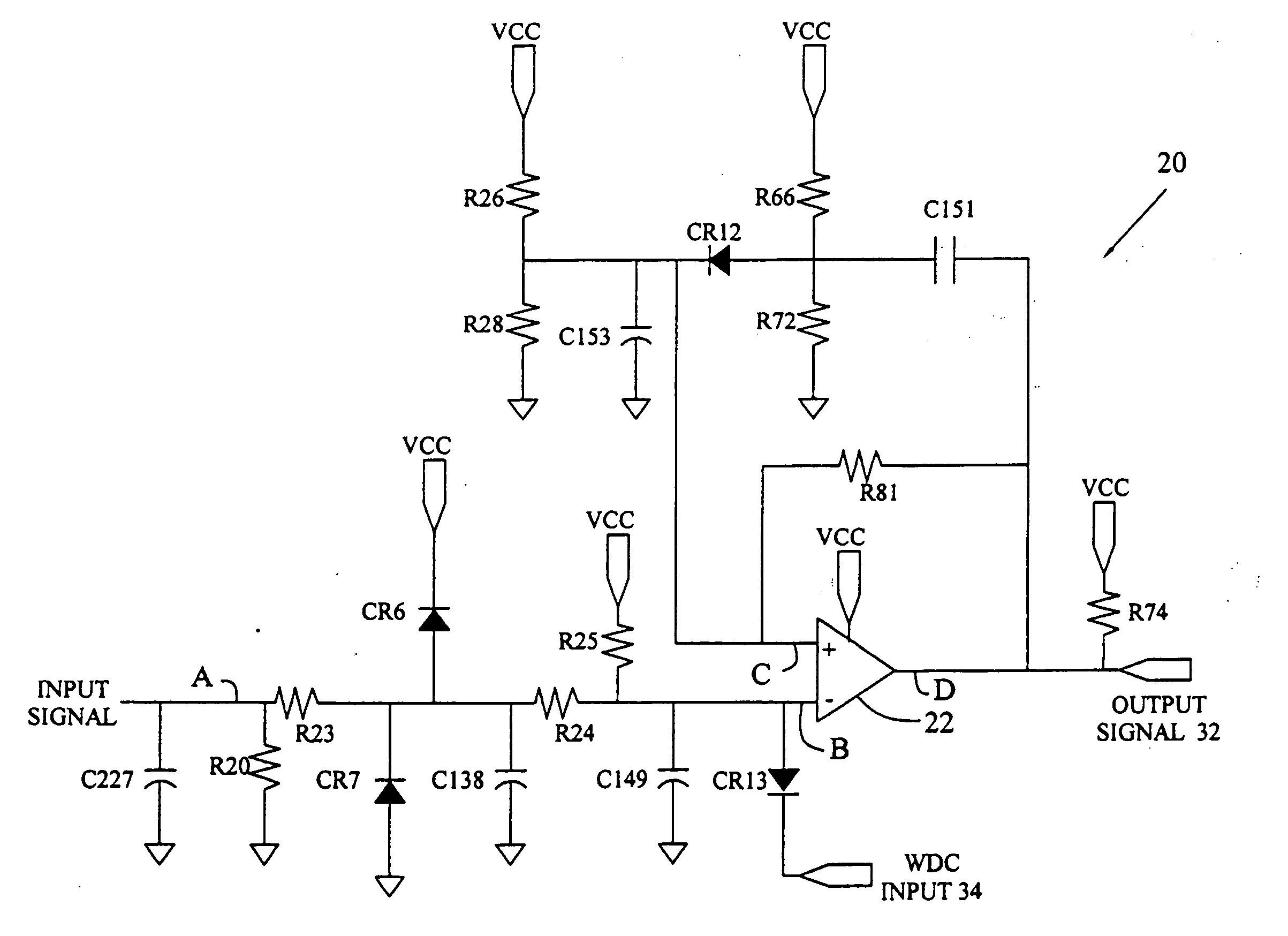
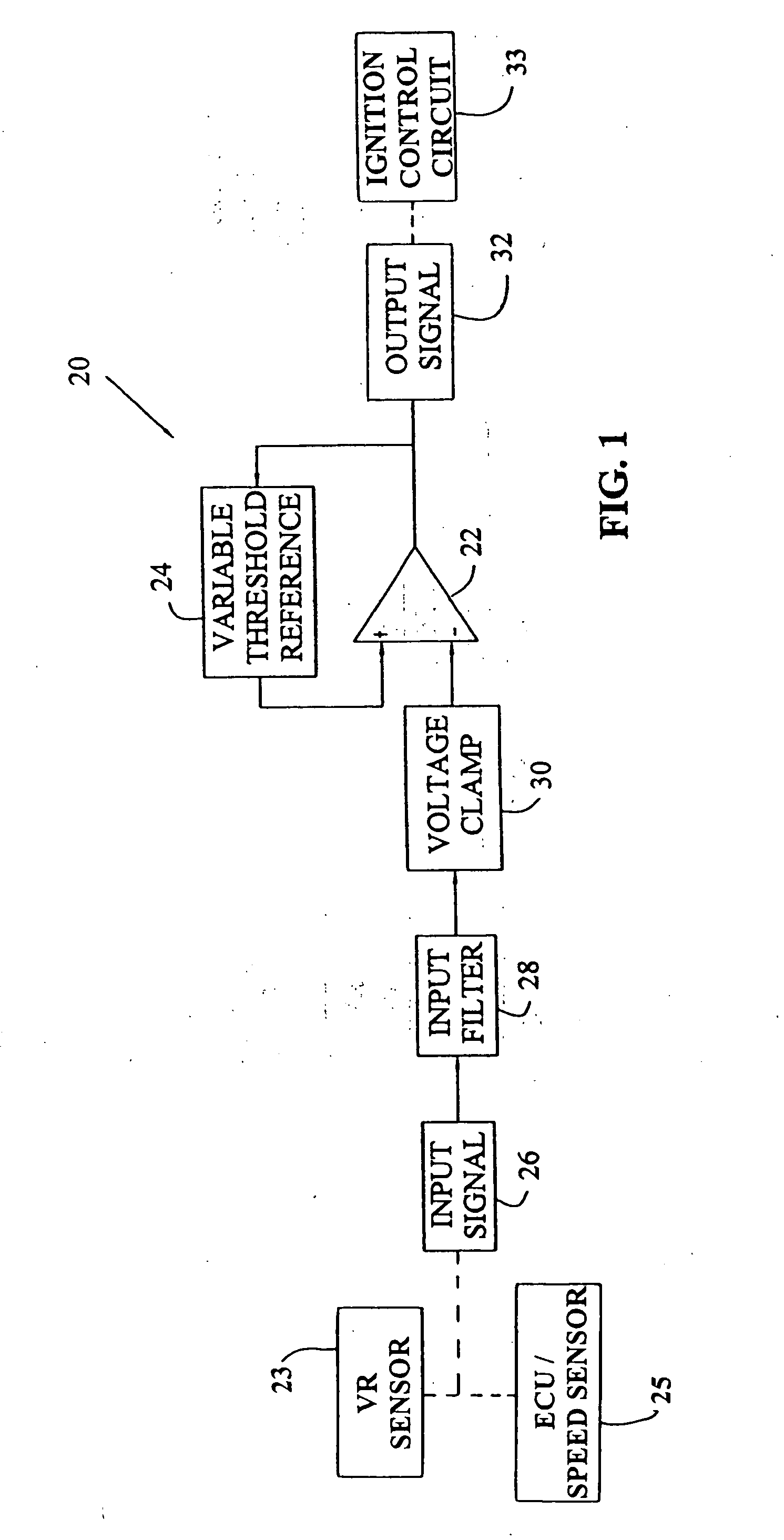
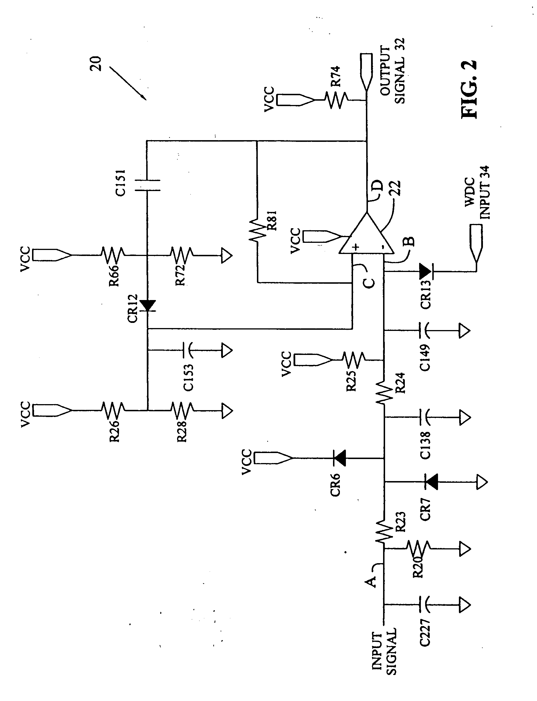
[0025] Referring to FIG. 1, exemplary signal detection circuit 20 provides signal processing of a quasi sinusoidal waveform, for example, a signal received from a variable reluctance (VR) sensor (not shown) used for detecting engine speed and position and used as a reference for an engine ignition signal. Exemplary circuit 20 provides an approximately square negative output pulse (active low) corresponding to the positive to negative zero crossing of a quasi-sinusoidal waveform component of input signal 26.

[0026] Output signal 32 of exemplary circuit 20 is a normally high output signal which is switched low upon a positive input pulse at the inverting input of comparator 22 exceeding the variable threshold re...


PUM


Abstract

A signal processing circuit with a comparator having a fixed and a variable reference input is provided for detection of a positive quasi-sinusoidal waveform pulse. The signal detection circuit includes a low pass input filter, a voltage input clamp, a variable detection threshold, and a zero crossing detector. The circuit produces an approximately square wave output substantially coinciding with the positive pulse of the quasi-sinusoidal waveform received, for example, from a variable reluctance sensor. The circuit may be used as a positive to negative zero crossing detector having detection armed by a variable threshold of the positive quasi-sinusoidal pulse, thus providing variable noise immunity and a fixed phase relationship between the input and output signal for an input signal having a variable amplitude.

Description

TECHNICAL BACKGROUND [0001] The present invention relates to a signal processing circuit, and more particularly to a signal detection circuit for automobile applications. BACKGROUND OF THE INVENTION [0002] Variable reluctance (VR) sensors are used in a number of automotive and nonautomotive applications. Automotive applications include engine speed and position sensing for ignition and transmission systems, and wheel speed sensing for anti-lock brake and traction control systems. [0003] A VR sensor includes an electromagnetic device having a coil, for example a winding of wire wrapped around a permanent magnet. The sensor is positioned near a rotating wheel having one or more ferrous notches or teeth. Rotation of the notches past the sensor coil provides a magnetic flux that creates a quasi-sinusoidal waveform in the sensor coil. The positive to negative zero crossing portion of the waveform typically is related to the center of the notch or tooth passing by the sensor tip. Sensing ...

Claims


Application Information

Patent Timeline
Patent Type & Authority Applications(United States)
IPC IPC(8): F02P7/077G01P3/481H03D1/00H03K5/08H03K5/1536
CPCF02P7/077H03K5/1536H03K5/088G01P3/481
Inventor BOYER, JOHN W.HARSHBARGER, DANIEL R.
Owner APTIV TECH LTD
Why Eureka
Try Eureka