Nonreciprocal device having heat transmission arrangement

a heat transmission arrangement and non-reciprocal technology, applied in the direction of electrical equipment, electrical apparatus, electrical apparatus contruction details, etc., can solve the problems of low reliability of handling and operation of two-portion structures, high labor amount and cost involved in assembly process, and complicated structure, etc., to achieve tight tolerances, high quality surfaces, and flat mounting bases.

Active Publication Date: 2005-06-23
RENAISSANCE ELECTRONICS & COMM LLC
View PDF3 Cites 1 Cited by
  • Summary
  • Abstract
  • Description
  • Claims
  • Application Information

AI Technical Summary

Benefits of technology

[0017] It is an advantage of the present invention that the pressed-on plug actually excludes any voids in the area of bimetallic contact, because for pressing fit the high quality surfaces and tight tolerances are intrinsically needed. That is easily achieving in the present invention by pressing a cylindrical plug and a round hole.
[0018] It is another advantage of the present invention that the flatness of the mounting base with tight tolerance requirement, or coplanarity, is easily achieved by pressing the plug into the housing using just the flat press plates. The usage of the flat plates in the pressing practice is very common and does not invoke any additional expenses.

Problems solved by technology

This structure, however, is pretty complex and does not cover the isolators wherein the resistive element, a termination—the most substantial source of the heat, is situated outside of the magnetic chamber.
The drawback of the structure is the complexity of the two-portion alignment (a close coplanarity tolerance of overall structure is needed to create a flat common surface of the mounting base) and, accordingly, relatively high labor amount and cost are involved in assembly process.
This two-portion structure also has lower reliability in handling and operation as compare with one portion housing devices.
There are also drawbacks in the design.
Firstly, part of the dissipation path still remains in a steel housing causing in operation a possibility for termination to be overheated.
Otherwise, in case of moisture, say, condensation, a detrimental galvanic couple of dissimilar metals can be formed in the voids, causing corrosion.

Method used


Image

  • Nonreciprocal device having heat transmission arrangement
  • Nonreciprocal device having heat transmission arrangement
  • Nonreciprocal device having heat transmission arrangement

Examples


Embodiment Construction

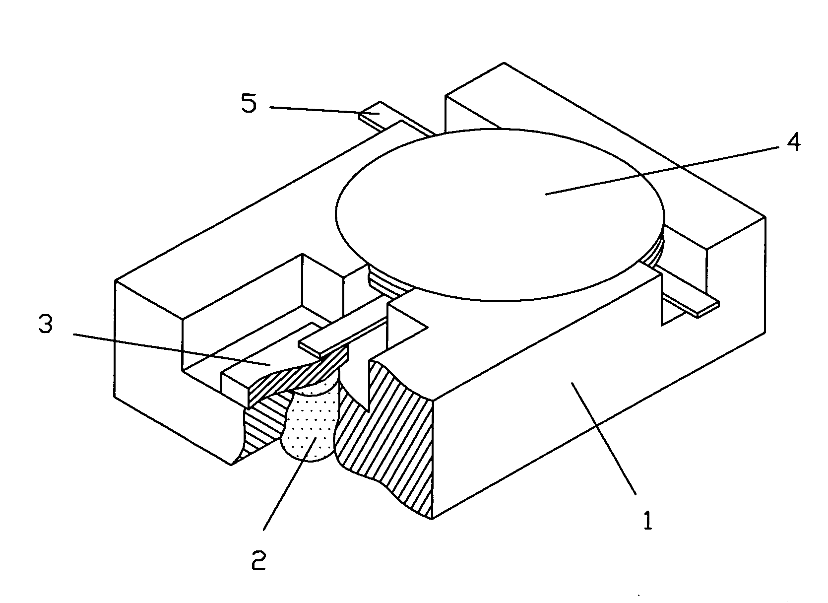
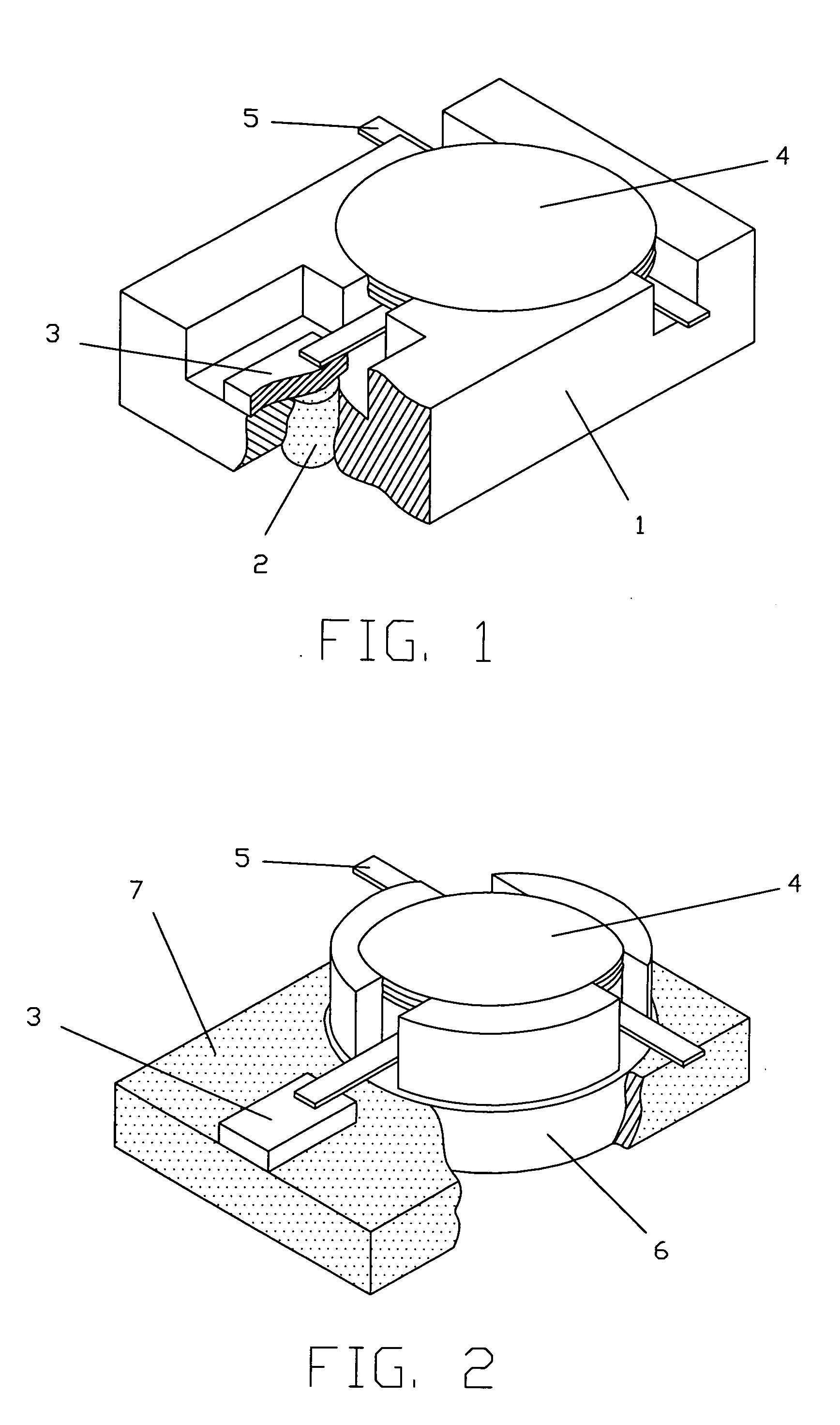
[0023] Referring to FIG. 1 the structure according to the present invention comprises a housing 1, a plug 2, a surface-mount resistive termination 3, a cover 4 and a central stuck 5 incorporating magnet, ferrite and the center conductor (only lead portions of central conductor are shown). There is a chamber (not shown) in the housing 1 wherein the assembly 5 is situated. The housing 1 is made of material having good magnetic susceptibility, for example mild steel, to provide an appropriate path for a magnetic flux in the chamber required for an isolator to work. The cover 4 also made of mild steel closes the chamber and magnetic flux loop. The chamber is often referred to as a magnetic chamber.

[0024] There is a through hole in the housing 1 completed with the plug 2 made of material having high coefficient of heat transmission, for example copper / aluminum. The plug 2 has a cylindrical shape with both ends perpendicular to its longitudinal axis. On top end (as shown) of the plug 2 t...


PUM


Abstract

An isolator with resistive termination and carbon steel housing wherein required magnetic performance is combined with improved efficiency of transmission of heat from termination to the heat sink. The improvement is achieved due to the copper / aluminum plug that mechanically and electrically connects the soldering base of termination to the base of isolator, which in operation is installed on the heat sink. The plug is pressed into the housing from the base side to provide tight coplanarity tolerance to exposed end of the plug and the base without any secondary machining. The termination is soldered to the opposite end of the plug, which is flush to or slightly above the top surface of the housing. Thus, magnetic flux required for operation of isolator is looped through a material having good magnetic susceptibility, and heat from the termination is transmitted to the heat sink through a material having high coefficient of heat transmission. Another embodiment of the structure is also described in this disclosure. In second embodiment, the entire housing is made of copper / aluminum, but a magnetic chamber of carbon steel supporting the magnetic loop is pressed into the housing. The termination is soldered directly to the housing and, therefore, the same efficiency for the heat dissipation as for the preferred embodiment is achieved.

Description

CROSS-REFERENCE TO RELATED APPLICATIONS [0001] Not applicable STATEMENT REGARDING FEDERALLY SPONSORED RESEARCH OR DEVELOPMENT [0002] Not applicable REFERENCE TO A MICROFICHE APPENDIX [0003] Not applicable BACKGROUND OF THE INVENTION [0004] The present invention relates generally to the microwave ferrite devices and more particularly to an improvement of heat transmission from a surface mount termination that is the main heat source in isolators, to the mounting base, which, in operation, is installed on a heat sink. It specifically relates to isolators having a resistive termination to shunt the reflected energy to the ground in combination with a ferromagnetic housing for closing a magnetic loop in magnetic chamber. [0005] There are contradictory requirements to the isolator housing in conducting the magnetic flux, and, at the same time, increasing the heat transmission. For a magnetic flux the housing made of mild steel is needed—the material having high magnetic susceptibility (μ...

Claims


Application Information

Patent Timeline
Patent Type & Authority Applications(United States)
IPC IPC(8): H01P1/36
CPCH01P1/36
Inventor GENFAN, GERMAN S.KOCHARYAN, KAREN
Owner RENAISSANCE ELECTRONICS & COMM LLC
Why Eureka
Try Eureka