
Apparatus for multiplexing Gigabit Ethernet frame and apparatus for demultiplexing 10-Gigabit Ethernet frame

Inactive Publication Date: 2005-06-23
ELECTRONICS & TELECOMM RES INST
View PDF7 Cites 17 Cited by
  • Summary
  • Abstract
  • Description
  • Claims
  • Application Information

AI Technical Summary

Benefits of technology

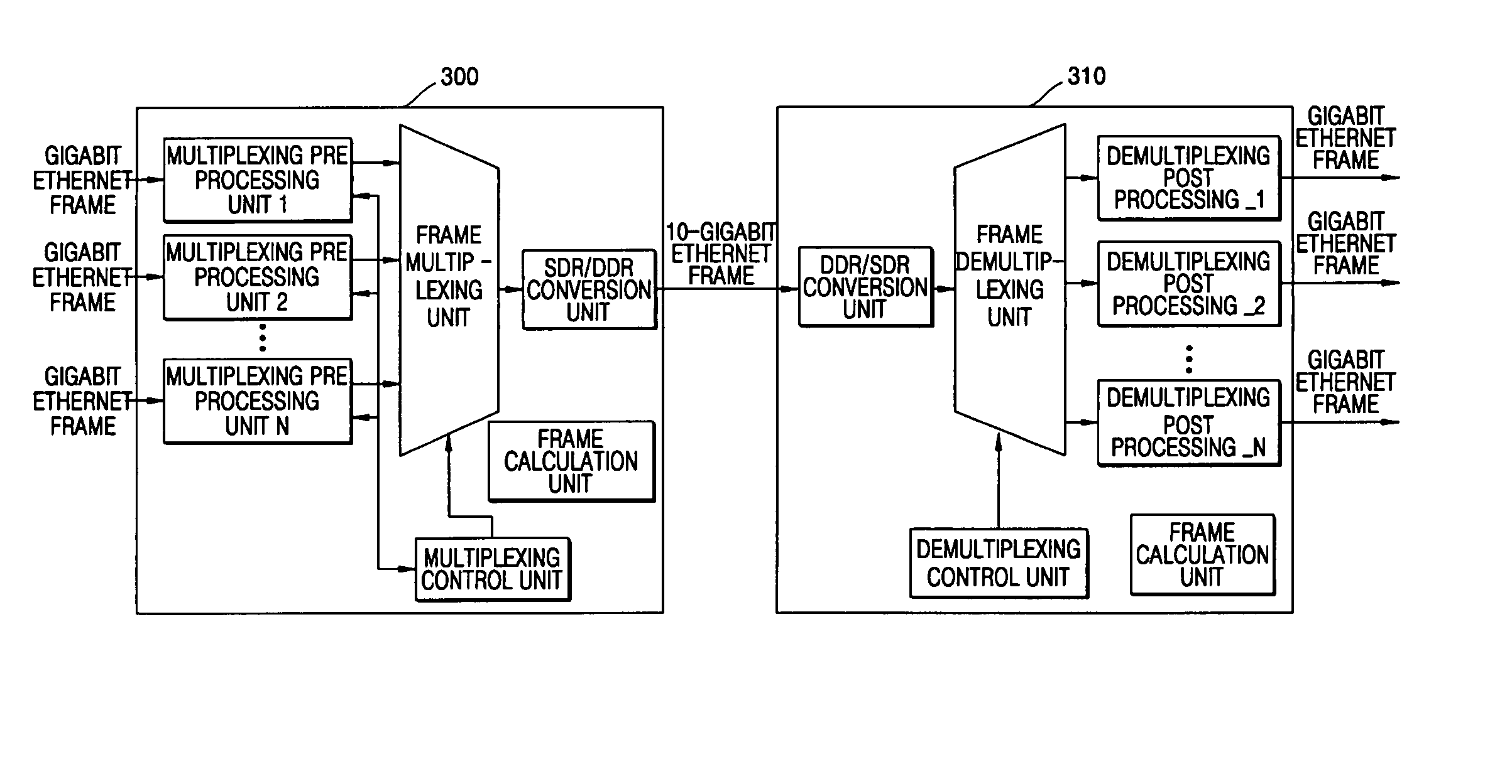
[0008] According to an aspect of the present invention, there is provided an apparatus for multiplexing Ethernet frames, the apparatus comprising: at least one pre-processing unit, which receives Gigabit Ethernet frames, converts the Gigabit Ethernet frames into 10-Gigabit Ethernet frames, and outputs the 10-Gigabit Ethernet frames; a multiplexing unit, which receives the 10-Gigabit Ethernet frames, time division multiplexes the 10-Gigabit Ethernet frames in frame units, and outputs the time division multiplexed 10-Gigabit Ethernet frames as first data; an SDR/DDR conversion unit, which converts the first data into second data having two 32-bit bus structures and outputs the second data; and a control unit, which outputs a first control signal in response to an output request of the pre-processing unit.
[0009] According to another aspect of the present invention, there is provided an appa

Problems solved by technology

Also, bit-based time division multiplexing (TDM) is considered, but when multiplexing is performed using bit-based TDM, it is difficult to synchronize frames and the multiplexed frames cannot maintain an Ethernet frame configuration, resulting in incompatibility with other Ethernet devices.
Also, since Ethernet frames have variable lengths ranging from 64 bytes to 1,518 bytes, when using the Ethernet frames in conventional cell-based multiplexing, there are many problems such as framing, synchronization, bit-based TDM, and the like.

Method used


Image

  • Apparatus for multiplexing Gigabit Ethernet frame and apparatus for demultiplexing 10-Gigabit Ethernet frame
  • Apparatus for multiplexing Gigabit Ethernet frame and apparatus for demultiplexing 10-Gigabit Ethernet frame
  • Apparatus for multiplexing Gigabit Ethernet frame and apparatus for demultiplexing 10-Gigabit Ethernet frame

Examples


Embodiment Construction

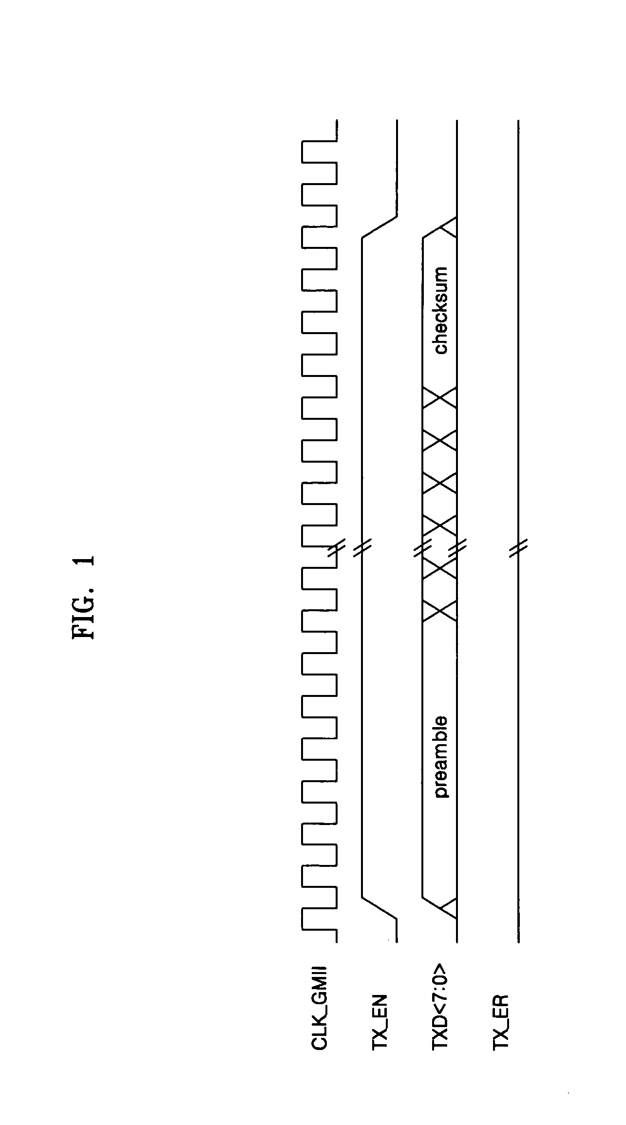
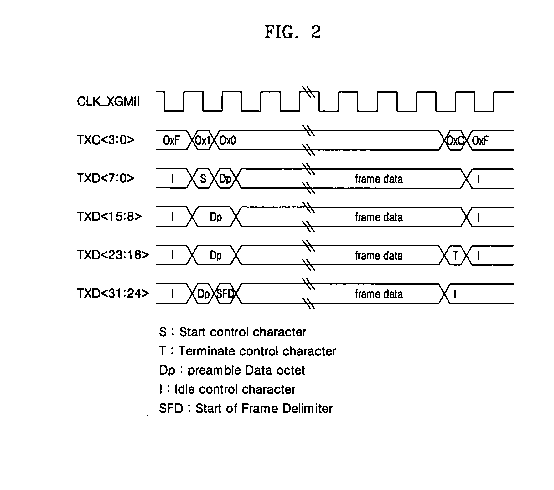
[0018] The present invention will now be described more fully with reference to the accompanying drawings, in which an embodiment of the invention is shown. Throughout the drawings, like reference numerals are used to refer to like elements. Hereinafter, timing diagrams for input / output operations of an apparatus for multiplexing Gigabit Ethernet frames and an apparatus for demultiplexing 10-Gigabit Ethernet frames will be described. FIG. 1 is a timing diagram of GMII standardized in IEEE802.3z and FIG. 2 is a timing diagram of XGMII standardized in IEEE802.3ae.

[0019] As shown in FIG. 1, GMII standardized in IEEE802.3z is composed of a 125 MHz clock CLK_GMII, a frame data enable signal TX_EN, an error signal TX_ER, and frame data TXD. To provide transmission rate of giga-bits per second, the frame data has 8-bit parallel configuration.

[0020] As shown in FIG. 2, XGMII standardized in IEEE802.3ae is composed of a 156.25 MHz clock CLK_XGMII, a 4-bit frame data control signal TXC corr...


PUM


Abstract

Provided are an apparatus for multiplexing Gigabit Ethernet frames and an apparatus for demultiplexing 10-Gigabit Ethernet frames. The apparatus for multiplexing Gigabit Ethernet frames includes at least one pre-processing unit, a multiplexing unit, an SDR / DDR conversion unit, and a control unit. The at least one pre-processing unit receives Gigabit Ethernet frames, converts the Gigabit Ethernet frames into 10-Gigabit Ethernet frames, and outputs the 10-Gigabit Ethernet frames. The multiplexing unit receives the 10-Gigabit Ethernet frames, time division multiplexes the 10-Gigabit Ethernet frames in frame units, and outputs the time division multiplexed 10-Gigabit Ethernet frames as first data. The SDR / DDR conversion unit, which converts the first data into second data having two 32-bit bus structures and outputs the second data. The control unit outputs a first control signal in response to an output request of the pre-processing unit.

Description

CROSS REFERENCE TO RELATED APPLICATION [0001] This application claims the priority of Korean Patent Application No. 2003-95388, filed on Dec. 23, 2003, in the Korean Intellectual Property Office, the disclosure of which is herein in its entirety incorporated by reference. BACKGROUND OF THE INVENTION [0002] 1. Field of the Invention [0003] The present invention relates to an apparatus for multiplexing Gigabit Ethernet frames to provide 10-Gigabit Ethernet interface by multiplexing Gigabit Ethernet frames input from multi-port Gigabit Ethernet MAC (Medium Access Control) and for demultiplexing 10-Gigabit Ethernet frame to provide Gigabit Ethernet interface to the multi-port Gigabit Ethernet MAC by demultiplexing the 10-Gigabit Ethernet frame. [0004] 2. Description of the Related Art [0005] Since Ethernet frames are not fixed-length cells used in asynchronous transfer mode (ATM) but have variable lengths ranging from 64 bytes to 1,518 bytes, fixed time slots cannot be used during a mul...

Claims


Application Information

Patent Timeline
IPC IPC(8): H04L12/20H04J3/04H04L12/66
CPCH04L12/66H04J3/04H04L12/16
Inventor CHOI, CHANG HOJOO, BHEOM SOONKIM, DO YEONJUNG, HAE WON
Owner ELECTRONICS & TELECOMM RES INST
Learn More