Battery pack

a battery pack and battery technology, applied in the field of batteries, to achieve the effect of reducing the volume energy density of the battery pack, maximizing the pack, and high pack energy density

Active Publication Date: 2005-06-23
MURATA MFG CO LTD
View PDF9 Cites 34 Cited by
  • Summary
  • Abstract
  • Description
  • Claims
  • Application Information

AI Technical Summary

Benefits of technology

[0011] According to an embodiment, the cell in the pack can be maximized, and hence a high pack energy density can be obtained, thus solving the conventional drawback in that, when the cell is placed in an outer covering molded case, a gap is formed between the case and the cell contained in the case to lower the volume energy density of the battery pack.
[0012] In an embodiment, since the battery element has an outer surface covered with a hard laminate film made of a metal, even without using a frame or the like on the side portion of the pack, the battery pack can keep a strength, a flaw resistance, and a satisfactory strength against penetration of a thumbtack or the like.
[0013] In an embodiemnt, merely a frame for holding a wiring board is needed, and the number of parts including an outer covering molded case can be reduced, thus considerably lowering the cost.
[0014] Differing from a conventional cell, the cell in an embodiment of the present invention can improve the strength.
[0015] The production of the cell part and the production of the pack part in an embodiment can be made through successive steps, thus shortening the time required for the production.

Problems solved by technology

Further, lithium ion polymer secondary batteries that have solved a drawback of leakage of liquid, which drawback may occur when using an electrolyte in a liquid state, for example, lithium ion polymer secondary batteries using, as an electrolyte, a gelled polymer film containing a polymer impregnated with a non-aqueous electrolytic solution, or an electrolyte in a solid state have been put into practical use.

Method used


Image

  • Battery pack
  • Battery pack
  • Battery pack

Examples


Embodiment Construction

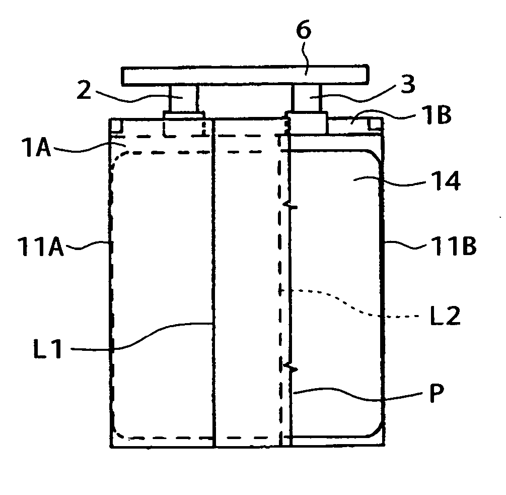
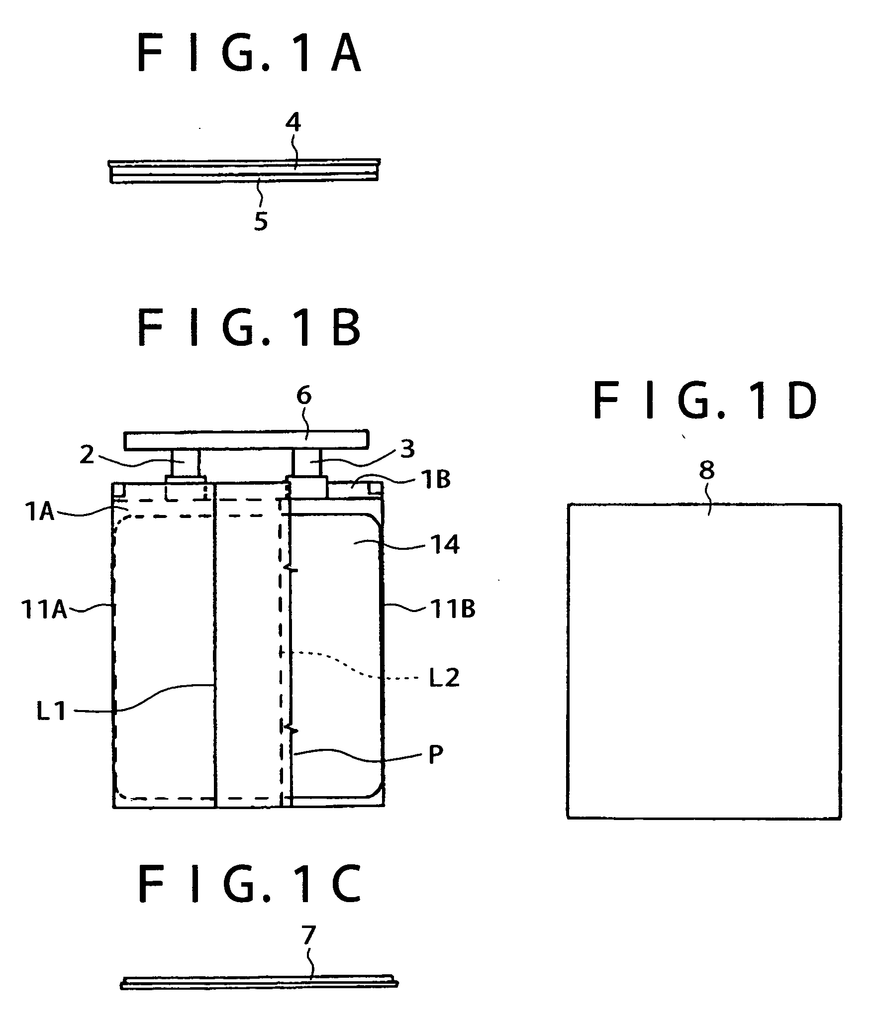
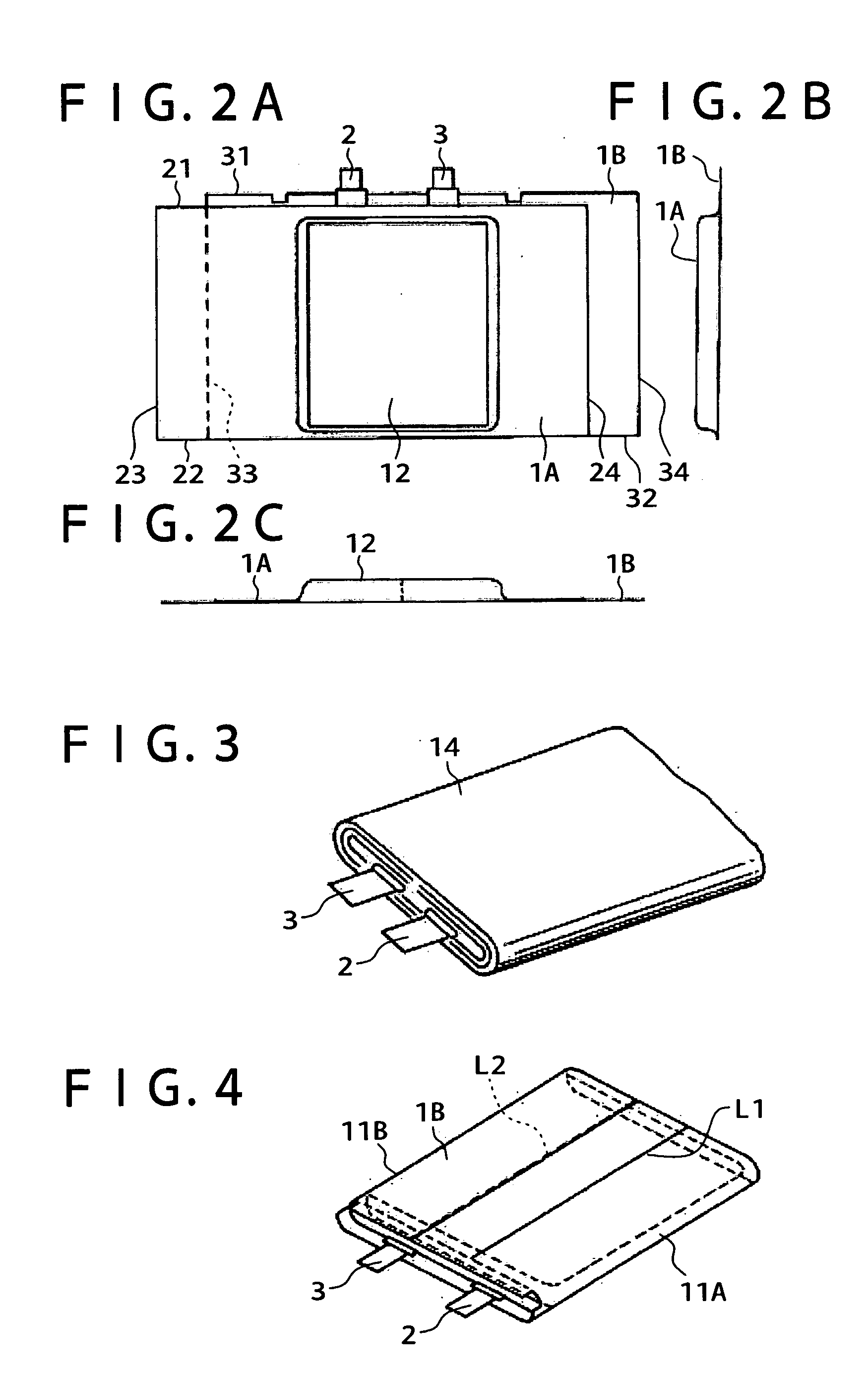
[0024] Hereinbelow, an embodiment of the present invention will be described with reference to the drawings. FIG. 1 shows the construction of a battery pack for a lithium ion polymer secondary battery to which the present invention is applied. Reference numerals 1A and 1B designate first and second laminate materials, respectively, and a battery element is covered with the laminate materials 1A and 1B to constitute a cell. The battery element corresponds to a lithium ion polymer secondary battery and, for example, has a plate form having a long side of 49 mm, a short side of 40 mm, and a thickness of 4.4 mm.

[0025] The laminate materials 1A and 1B, as described below, constitute a film of a three-layer structure including a bonding layer and a surface protective layer formed on both surfaces of a metal layer. The surface protective layer of the laminate material 1B appears entirely on the outer surface of the cell. FIG. 1B shows a state in which a battery element 14 is exposed by cu...


PUM

PropertyMeasurementUnit
thicknessaaaaaaaaaa
thicknessaaaaaaaaaa
thicknessaaaaaaaaaa

Abstract

A battery pack which can increase of the volumetric efficiency of the battery pack without being contained in a resin mold case is provided. A first laminate material has a concave portion formed by drawing where a battery element is contained. A second laminate material is stacked so as to cover the opening of the concave portion to seal up the periphery of the opening. The first and second laminate materials are bend inwards so as to cover the battery element, and bonded and fixed together by heating. The first laminate material has three-layer structure including a polypropylene layer, a soft aluminum layer, and a nylon layer or PET layer. The second laminate material has a similar structure but includes a hard aluminum layer. Therefore, the second laminate material has enough strength to resist deformation without being contained a cell in a resin mold case.

Description

CROSS REFERENCES TO RELATED APPLICATIONS [0001] This application claims priority to Japanese Patent Document No. JP2003-385287, filed in the Japanese Patent Office on Nov. 14, 2003, the disclosure in its entirety of which is incorporated herein by reference. BACKGROUND OF THE INVENTION [0002] The present invention relates to a battery pack used in, for example, a lithium ion polymer secondary battery. [0003] Recently, portable electronic apparatuses, such as a laptop personal computer, a mobile phone, and a PDA (personal digital assistant), have been spread, and, as a power source for the apparatuses, a lithium ion battery having advantages, such as high voltage, high energy density, and being lightweight, is widely used. [0004] Further, lithium ion polymer secondary batteries that have solved a drawback of leakage of liquid, which drawback may occur when using an electrolyte in a liquid state, for example, lithium ion polymer secondary batteries using, as an electrolyte, a gelled p...

Claims


Application Information

Patent Timeline
Patent Type & Authority Applications(United States)
IPC IPC(8): H01M6/50H01M10/00H01M10/04H01M10/0525H01M10/0565H01M10/36H01M10/42H01M50/119H01M50/121H01M50/129H01M50/133H01M50/134H01M50/14
CPCH01M2/0257H01M2/0426H01M10/0431H01M10/0436Y02E60/122H01M10/0565H01M10/425H01M2200/00H01M10/0525Y02E60/10H01M50/169Y02P70/50H01M50/133H01M50/121H01M50/14H01M50/129H01M50/134H01M50/119H01M50/20
Inventor YAMADA, HIROYUKITOGASHI, KAZUOISHII, TORUYAMAHIRA, TAKAYUKISUZUKI, FUMIHIKO
Owner MURATA MFG CO LTD
Why Eureka
Try Eureka