Mass flow grain monitor and method

a grain monitor and mass flow technology, applied in the field of grain monitors, can solve the problems of introducing errors into the output data, affecting the quality of grain, and affecting the quality of grain, and achieve the effect of simple yet effectiv

Active Publication Date: 2005-06-23
AGCO CORP
View PDF19 Cites 11 Cited by
  • Summary
  • Abstract
  • Description
  • Claims
  • Application Information

AI Technical Summary

Benefits of technology

[0004] The present invention provides a simple yet effective way of dealing with the hillside problem. Rather than measuring the force of the grain flow horizontally after it leaves the clean grain elevator as in some conventional systems, the present invention contemplates measuring the force vertically as it moves around the upper end of the elevator and generates a centrifugal force. The load member of the cell is arranged generally horizontally such that its weight is directly opposite to the generally vertical centrifugal force being generated by the grain flow as it changes directions from vertical to horizontal. This weight can be easily zeroed out as tare during calibration. More importantly, with this arrangement the change in tare during hillside operations is much smaller than in conventional arrangements because the change is proportional to the trigonometric cosine of the hillside angle rather than the sine. Prior art devices which essentially measure the flow force horizontally introduce an error that is proportional to the change of the sine of the hillside angle.

Problems solved by technology

In installations that use load cells, the load member's own weight tends to deform the member to a slight extent, introducing errors into the output data unless the weight (tare) of the member is “zeroed out” during initial calibration of the unit.
While such calibration is effective so long as the harvester remains on a level surface, problems arise when the harvest encounters up slopes or downslopes during hillside operations.
Some machines have included inclinometers which detect inclination of the harvester and provide appropriate input to computers that process the information to deal with the hillside, but systems of that type can be fairly complex and costly.
Prior art devices which essentially measure the flow force horizontally introduce an error that is proportional to the change of the sine of the hillside angle.

Method used


Image

  • Mass flow grain monitor and method
  • Mass flow grain monitor and method
  • Mass flow grain monitor and method

Examples


Embodiment Construction

[0016] The present invention is susceptible of embodiment in many different forms. While the drawings illustrate and the specification describes certain preferred embodiments of the invention, it is to be understood that such disclosure is by way of example only. There is no intent to limit the principles of the present invention to the particular disclosed embodiments.

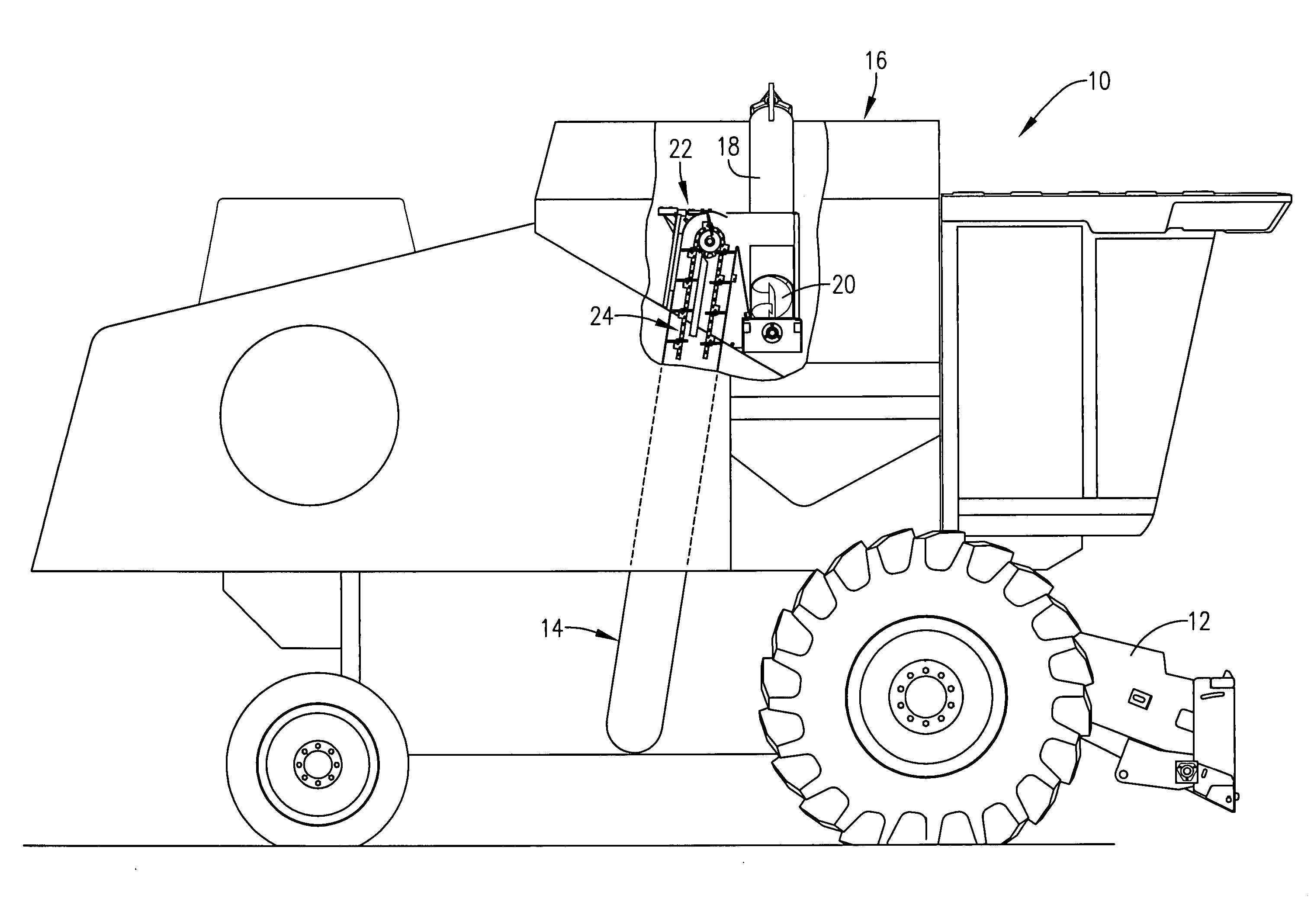
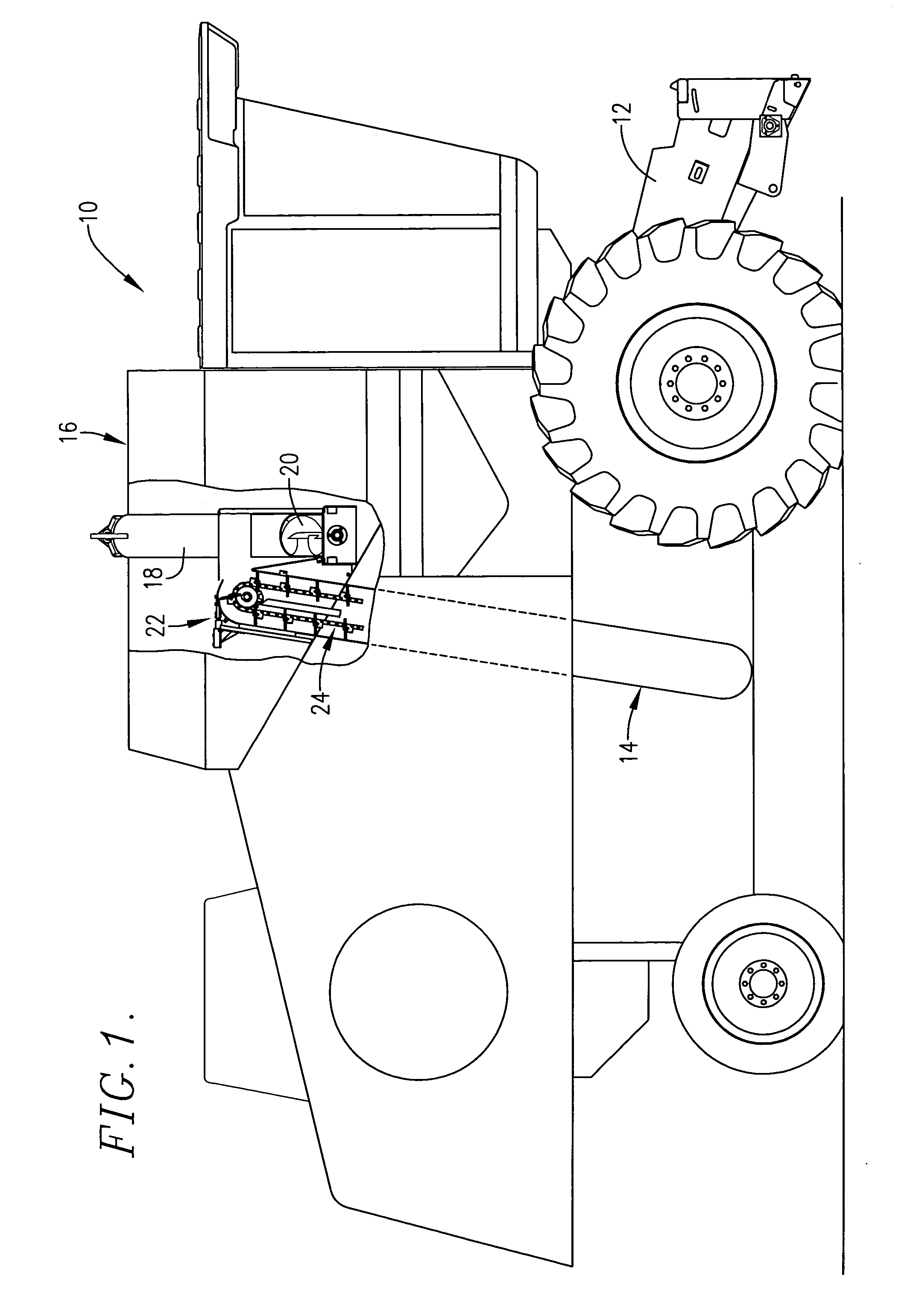
[0017] The combine harvester 10 in FIG. 1 is illustrated without a harvesting header attached to the lower front end of feeder housing 12. During harvesting operations, however, a header of suitable design is supported at the front end feeder housing 12 and directs harvested materials into the same for subsequent processing by internal threshing and cleaning mechanism of the harvester. Generally speaking, waste products such as straw, stalks, leaves, husks, hulls and chaff exit the machine through the rear thereof while clean grain is directed to a clean grain elevator assembly 14 near the bottom of the machine and e...


PUM


Abstract

A mass flow grain monitor is located adjacent the upper end of the clean grain elevator assembly of a harvester and includes a load cell having a member that is subject to slight deformation under loads for use in generating an output signal that is proportional to the load. As the grain flow reaches the top of the elevator assembly, its direction is changed such that a centrifugal force is exerted by the moving flow that is proportional to the mass of the grain flow at that instant. Such centrifugal force is directed vertically against the deformable member of the load cell which is itself generally horizontally disposed when the harvester is on level ground so that the entire weight of the deformable member can be treated as tare and zeroed out of the system when it is calibrated with the harvester on level ground. Having the member generally horizontally disposed and measuring the force of the grain vertically causes a significant reduction in the amount of error introduced into the output from the monitor when the harvester encounters upsloping or downsloping hillside conditions.

Description

TECHNICAL FIELD [0001] This invention relates to harvesting equipment, and more particularly, to grain monitors used on combine harvesters and the like for continuously monitoring the clean grain throughput of the machine. BACKGROUND AND SUMMARY [0002] Grain monitors for combine harvesters are known in the art. It is also known in the art to utilize a load cell as part of such a monitor wherein a Wheatstone bridge or the like is utilized to detect minute deformations of a member of the cell that occur when clean grain from an elevator of the harvester impacts or otherwise exerts a load on the member. [0003] In installations that use load cells, the load member's own weight tends to deform the member to a slight extent, introducing errors into the output data unless the weight (tare) of the member is “zeroed out” during initial calibration of the unit. While such calibration is effective so long as the harvester remains on a level surface, problems arise when the harvest encounters u...

Claims


Application Information

Patent Timeline
Patent Type & Authority Applications(United States)
IPC IPC(8): A01D41/127A01D75/28
CPCA01D41/1271A01F12/46A01D75/28A01D41/1272
Inventor MURRAY, DAVID L.CASE, MICHAEL D.
Owner AGCO CORP
Why Eureka
Try Eureka