
Drilling microneedle device

a microneedle and drill bit technology, applied in the field of injection/extraction devices, can solve problems such as serious infection risk, and achieve the effect of preventing injury to patients and better controlling the penetration depth

Inactive Publication Date: 2005-06-23
GEORGIA TECH RES CORP +1
View PDF9 Cites 205 Cited by
  • Summary
  • Abstract
  • Description
  • Claims
  • Application Information

AI Technical Summary

Benefits of technology

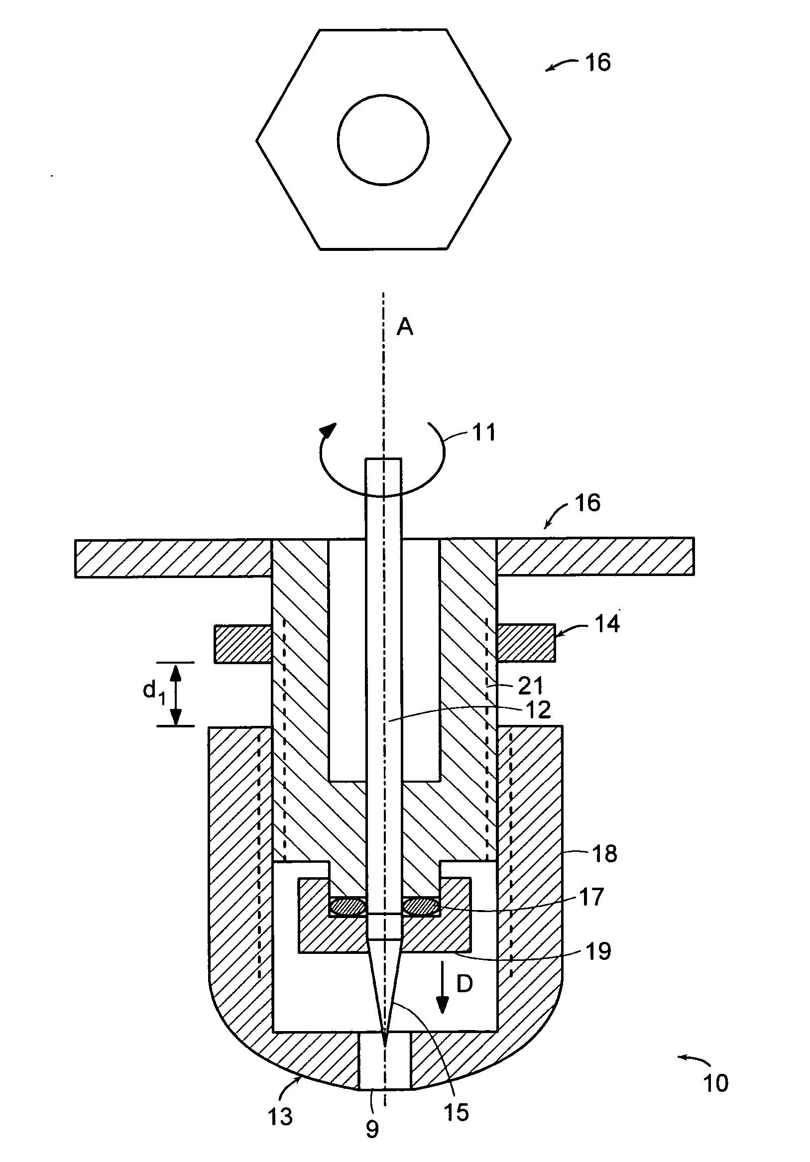
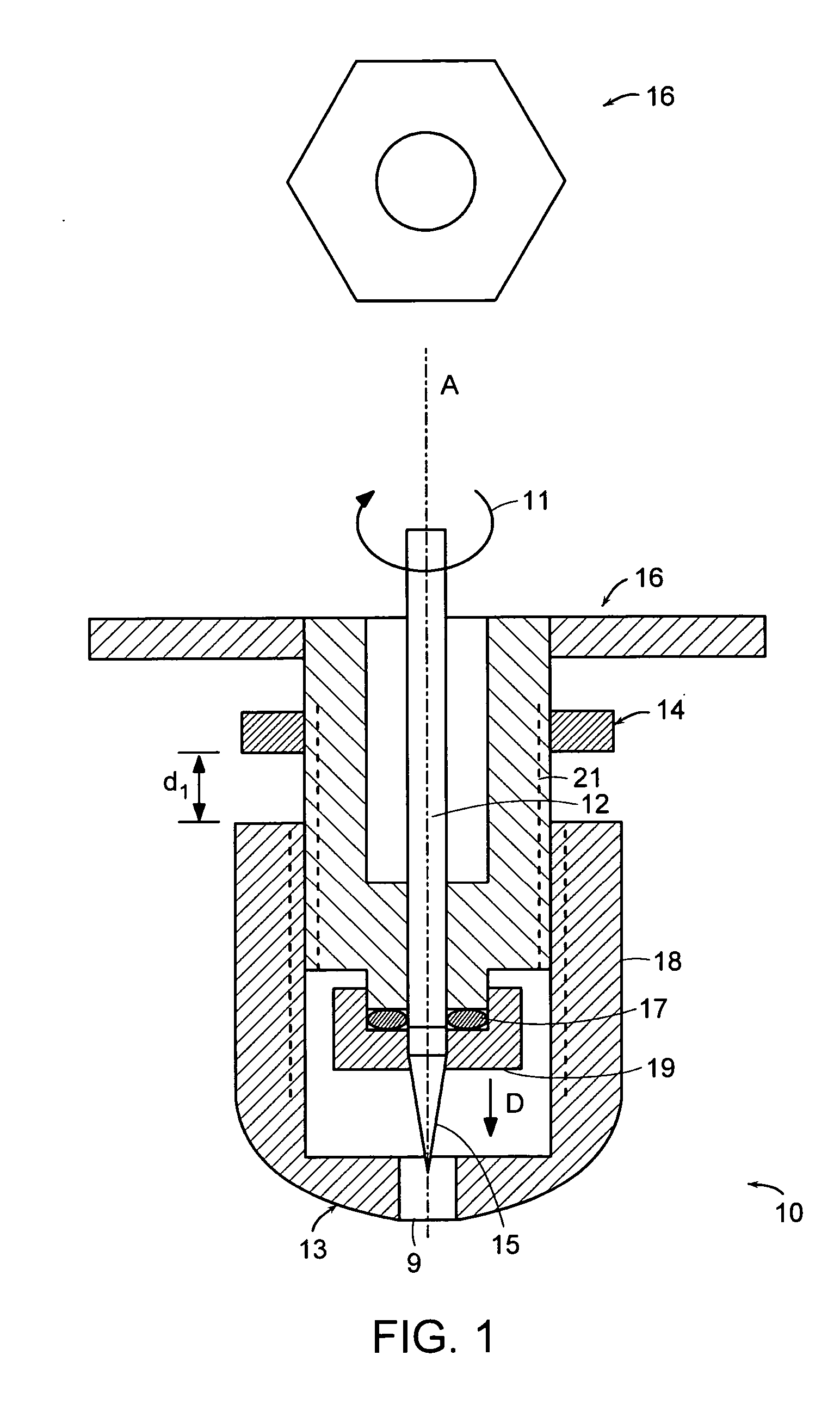
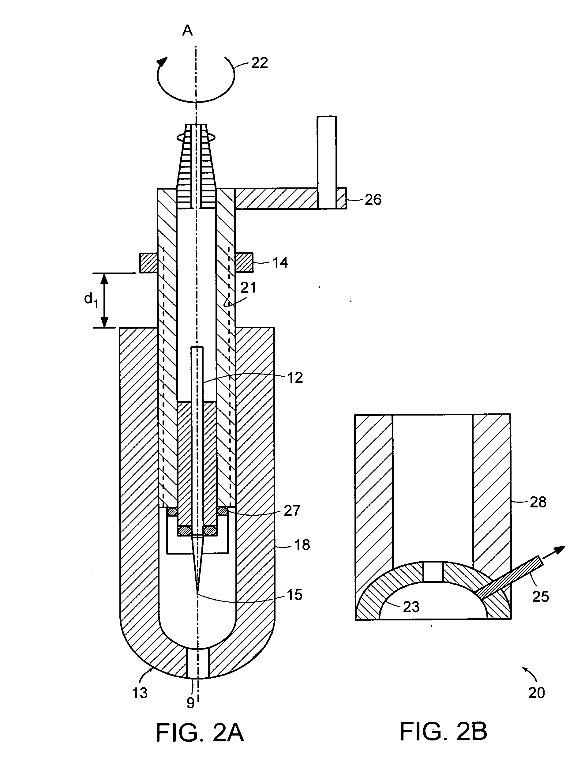
The invention is about a device called a microneedle that can be used to penetrate biological barriers such as skin for various purposes like drug delivery, monitoring glucose levels, and intracellular gene transfer. The device has a rotating or drilling microneedle that can be controlled to penetrate the barrier and has various shapes such as blunt, sharp, or beveled. The device can be made with materials like glass or metal and can have a plastic coating for added rigidity. The device can also be designed to cooperate with a ballpoint pen-shaped applicator or a suction cup-shaped tip for controlled injection. The invention provides a better method for controlling the penetration depth of the microneedle and can help to prevent injury to the patient.

Problems solved by technology

Certain conditions, such as diabetes and other chronic conditions, can be especially taxing because they require ongoing diagnostic and therapeutic intervention which may not only be inconvenient and / or painful, but also pose a serious risk of infection.

Method used


Image

  • Drilling microneedle device
  • Drilling microneedle device
  • Drilling microneedle device

Examples


example 1

Drilling Hairless-Skin with Microneedle Device

[0137] An area of rat skin was shaved to remove hair and reveal the skin surface underneath. A microneedle device as depicted in Figure xxx was used to drill holes on the hairless skin area, using a microneedle with a maximum drilling depth of about 800 μm.

[0138]FIG. 14 shows, at two different magnification, that a single hole with a relatively round shape was generated after drilling. FIG. 15 is a cross-section of the hole shown in FIG. 14, obtained by freezing the drilled hole and sectioning using microtome. The figure shows that the drilling left in the skin a hole with a depth of about 730 μm, and a diameter of about 87 μm at the surface of the skin.

example 2

Drilling Hairless-Skin with Microneedle Device, and ISF Collection

[0139] An area of bare skin was prepared as above. After drilling 3-10 points in the general area, a vacuum pressure of about −200 to −500 mmHg was applied to the area with drilled holes, for about 5-10 minutes. After suction, small interstitial fluids (ISF) and blood droplets appeared at the skin surface. The ISF collected through the vacuum, which was about 700 nL total in volume, turned out to be sufficient for glucose level monitoring using a standard glucose monitoring device, such as the FreeStyle™ blood glucose sensor (TheraSense, Alameda, Calif.). The measured glucose level is identical to the blood glucose level.

[0140]FIG. 17 shows a cross-section of the bare rat skin drilled for fluid extraction.

example 3

Drilling Hairless-Skin with Microneedle Device and Fluid Microinjection

[0141] An area of bare skin was prepared as above. Tissue blue dye (marker) was prepared as 20% solution in PBS, and infusion of the dye solution through the subject microneedle device lasted about 5 minutes under a positive pressure of about 10 psi. The injected skin specimen was cut off and frozen in liquid N2, and then sectioned using microtome to reveal the depth the dye reached. FIG. 16 shows that the deepest reach of the dye was about 370 μm, indicating that the subject device can be used to control the distance of needle reach, such that an automatic drug injection with a pre-determined depth can be achieved.


PUM


Abstract

Rotating microneedles and microneedle arrays are disclosed that “drill” holes into a biological barrier, such as skin. The holes can of controlled depth and diameter and suitable for microsurgery, administering drugs and withdrawal of body fluids.

Description

REFERENCE TO RELATED APPLICATIONS [0001] This application claims the benefit of the filing date of U.S. Provisional Application No. 60 / 476,015, filed on Jun. 4, 2003, the entire content of which is incorporated herein by reference.STATEMENT REGARDING FEDERALLY SPONSORED RESEARCH AND DEVELOPMENT [0002] This invention was made with government support under Contract Number 1 R01 GM 60004-01A1, awarded by the National Institute of Health (NIH). The United States Government has certain rights in this invention.BACKGROUND OF THE INVENTION [0003] The invention relates to injection / extraction devices, especially devices using a rotating microneedles, and to methods of using the same. [0004] Delivery of drugs to a patient (e.g. human and other non-human animals) can be performed in a number of ways. For example, intravenous delivery is by injection drugs directly into a blood vessel of the patient; intraperitoneal delivery is by injection into the peritoneum; subcutaneous delivery is under t...

Claims


Application Information

Patent Timeline
Patent Type & Authority Applications(United States)
IPC IPC(8): A61B10/00A61B10/02A61M5/32A61M5/42A61M37/00
CPCA61B10/0283A61M5/425A61M37/0015A61M2005/3289A61M5/46A61M2037/003A61M2037/0038A61M2037/0053A61M2037/0023A61M5/3298
Inventor WANG, PING MINGPRAUSNITZ, MARK R.
Owner GEORGIA TECH RES CORP
Learn More