
Method of forming a lead

a lead and lead-forming technology, applied in the field of lead, can solve the problems of least undesirable variance in lead diameter, too rigid and even brittle regions, etc., and achieve the effect of reducing energy consumption and low resistance during system operation

Inactive Publication Date: 2005-06-30
BLACK DAMON RAY +4
View PDF99 Cites 61 Cited by
  • Summary
  • Abstract
  • Description
  • Claims
  • Application Information

AI Technical Summary

Benefits of technology

[0016] Another object of the present invention is to provide a lead having a low resistance from a terminal to a coupled electrode to reduce energy consumption during system operation.

Problems solved by technology

While this technique does typically effect stabilization and strengthening of these critical regions, the end result can also be that these regions are too rigid and even brittle.
Element misalignment, inaccuracies in grinding, variances in electrode material thickness or individual element dimensions, or over / under-crimping could respectively result in at least undesirable variances in lead diameter.

Method used


Image

  • Method of forming a lead
  • Method of forming a lead
  • Method of forming a lead

Examples


Embodiment Construction

[0030] Various embodiments, including preferred embodiments, will now be described in detail below with reference to the drawings:

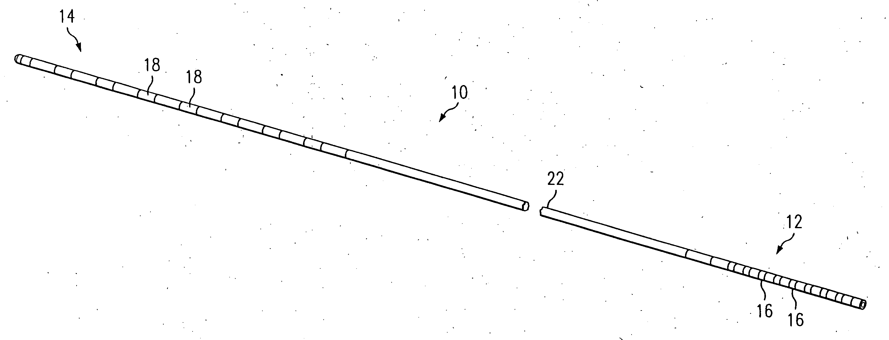
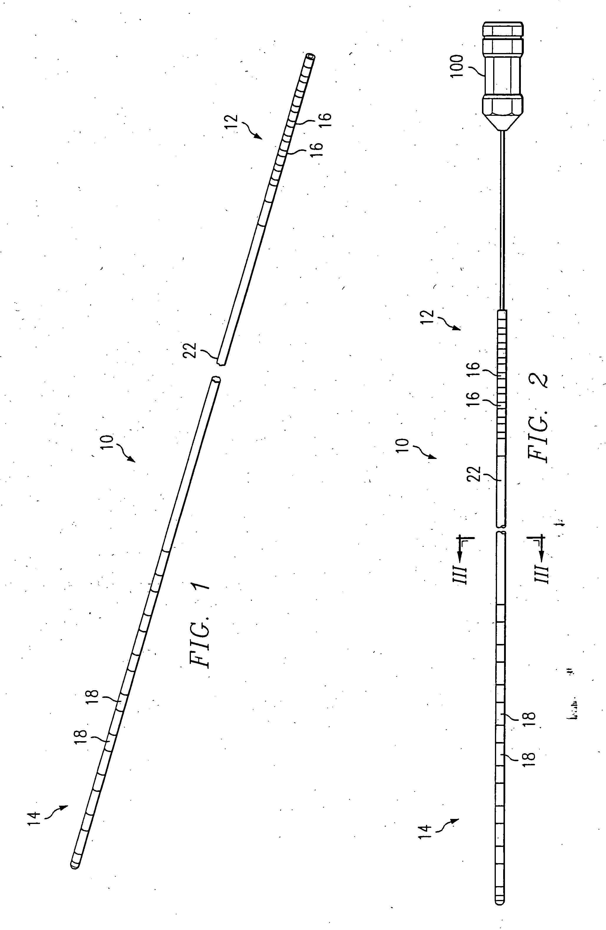
[0031]FIG. 1 illustrates a preferred embodiment of multi-electrode lead 10. While the leads illustrated and generally discussed here have eight electrodes, lead 10 of the present invention may be constructed having any number of electrodes (i.e., one or more):

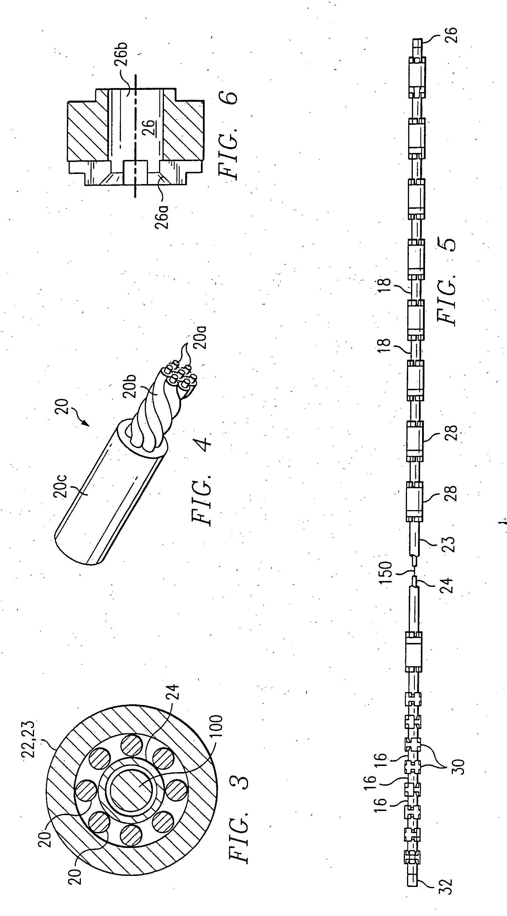
[0032] Lead 10 includes a proximal end 12 and a distal end 14. The proximal end 12 includes a plurality of electrically conductive terminals 16, and the distal end 14 includes a plurality of electrically conductive electrodes 18. While typically each terminal 16 is electrically connected to a single electrode 18 via a conductor 20 (FIG. 3), a terminal 16 can be connected to two or more electrodes 18.

[0033] Terminals 16 and electrodes 18 are preferably formed of a non-corrosive, highly conductive material. Examples of such material include stainless steel, MP35N, platinum, and platinum alloys. In a...


PUM

PropertyMeasurementUnit
lengthaaaaaaaaaa
resistanceaaaaaaaaaa
outer diameteraaaaaaaaaa

Abstract

An implantable, substantially isodiametric, low resistance implantable lead having at least one electrode positioned in a stimulation / sensing portion of the lead as well as a method of manufacturing the same. At least the stimulation / sensing portion is unitized through partially surrounding and supporting insulation and conductive element(s) of the stimulation / sensing portion with a fused matrix of material having mechanical properties consistent with a body of the lead.

Description

RELATED APPLICATIONS [0001] This is a division of U.S. patent application Ser. No. 09 / 760,437, filed Jan. 12, 2001, pending, which is a division of U.S. patent application Ser. No. 09 / 299,702, filed Apr. 26, 1999, issued as U.S. Pat. No. 6,216,045.FIELD OF THE INVENTION [0002] The present invention relates to a lead, and in particular, to an implantable lead and a method of manufacturing such lead. BACKGROUND OF THE INVENTION [0003] Implantable leads having ring electrodes can be used in a variety of applications, including delivery of electrical stimulation to surrounding tissue, neural or otherwise, as well as measuring electrical energy produced by such tissue. Whether serving in a stimulation capacity or a sensing capacity, such leads are commonly implanted along peripheral nerves, within the epidural or the intrathecal spaces of the spinal column, about the heart, and in the brain. [0004] Notwithstanding the application, the common requirements for such implantable leads includ...

Claims


Application Information

Patent Timeline
Patent Type & Authority Applications(United States)
IPC IPC(8): A61B5/0408A61B5/0478A61N1/05
CPCY10T29/49208Y10T29/4922A61N1/05Y10T29/49176Y10T29/49117Y10T29/49002A61N1/0551A61N1/056Y10T29/49174Y10T29/49204H01R43/00
Inventor BLACK, DAMON RAYDAGLOW, TERRYERICKSONJONES, ROBERT EARLLAURO, B. RENO
Owner BLACK DAMON RAY
Features
  • Generate Ideas
  • Intellectual Property
  • Life Sciences
  • Materials
  • Tech Scout
  • Unparalleled Data Quality
  • Higher Quality Content
  • 60% Fewer Hallucinations
Learn More