Solid-state image pickup apparatus and image pickup method

a solid-state image and pickup apparatus technology, applied in the direction of color television details, color signal processing circuits, television systems, etc., can solve the problems of large invalid area, power consumption and accuracy, and degradation of analog circuit systems in terms of noise, power consumption and accuracy, and achieve high degree of accuracy and efficient correction

Inactive Publication Date: 2005-06-30
SONY CORP
View PDF1 Cites 43 Cited by
  • Summary
  • Abstract
  • Description
  • Claims
  • Application Information

AI Technical Summary

Benefits of technology

[0009] It is an object of the present invention to provide a solid-state image pickup apparatus and an image pickup method by which fixed pattern noise can be detected and corrected efficiently with a high degree of accuracy.

Problems solved by technology

However, if the processing frequency is raised simply in order to process a greater number of pixels at a higher speed, then this gives rises to a problem of degradation of an analog circuit system in terms of noise, power consumption and accuracy.
However, a dispersion in a production process or the like gives rise to a problem that it causes a dispersion in inputting and outputting characteristics in such parallel reading out as described above, resulting in generation of fixed pattern noise including a striped defect on an output image.
However, in order to accurately recognize fixed pattern noise in the form of a vertical stripe, a large invalid area is required in addition to a valid image area.
This, however, acts negatively in high speed image pickup.
Further, from a characteristic of digital arithmetic operation, a limit to correction by a gradation upon A / D conversion is provided by a quantization error, an arithmetic operation rounding error and so forth.
Particularly in a system which has an A / D converter of a low gradation, this correction limit matters and sometimes makes the noise cancellation insufficient.
Further, although it is preferable to use a number of pickup image signals as great as possible for addition and averaging in order to improve the accuracy of a value to be stored as fixed pattern noise, this increases the value of the added average and increases the required memory capacity, which is not efficient.

Method used


Image

  • Solid-state image pickup apparatus and image pickup method
  • Solid-state image pickup apparatus and image pickup method
  • Solid-state image pickup apparatus and image pickup method

Examples


first embodiment

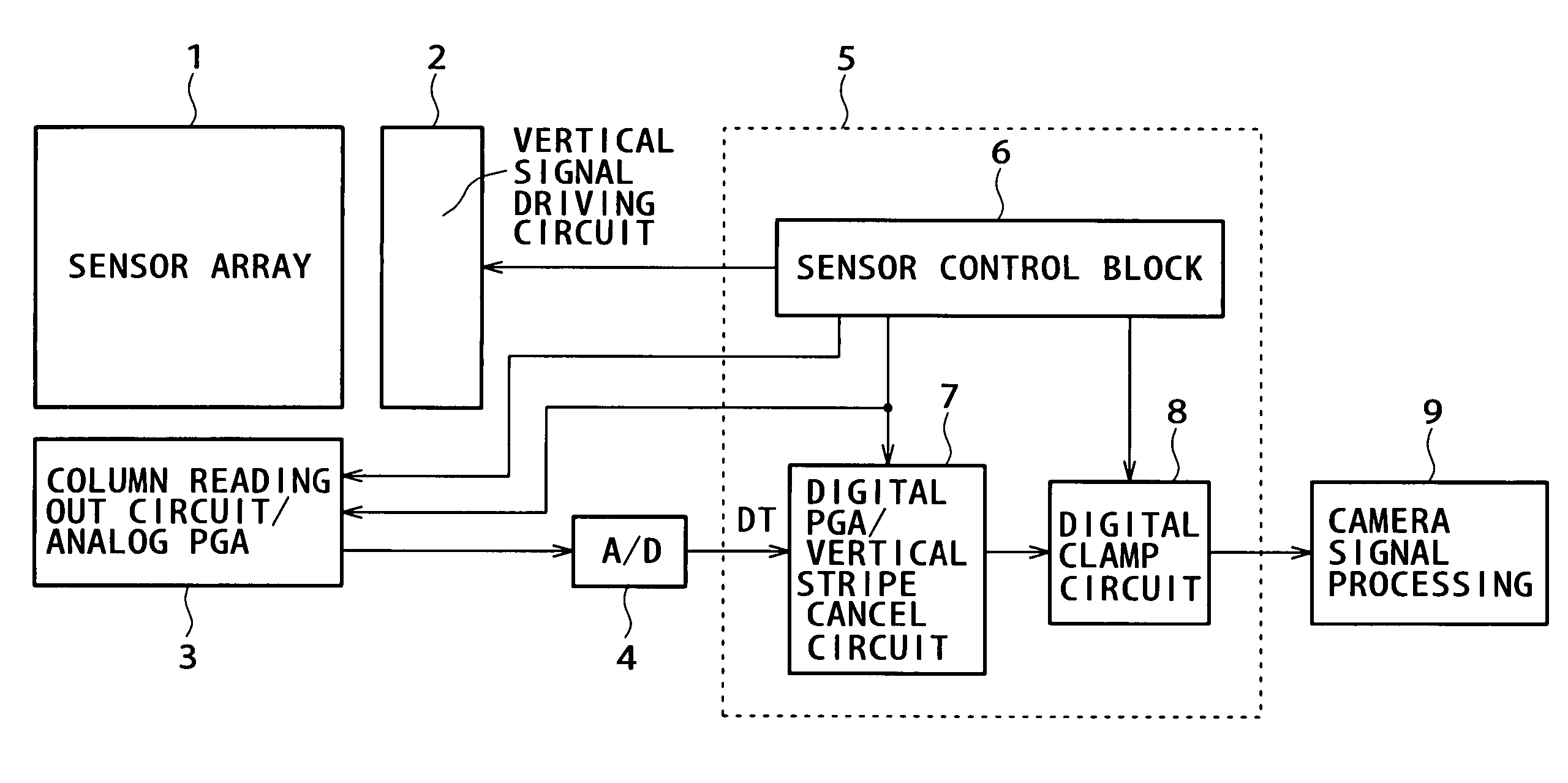
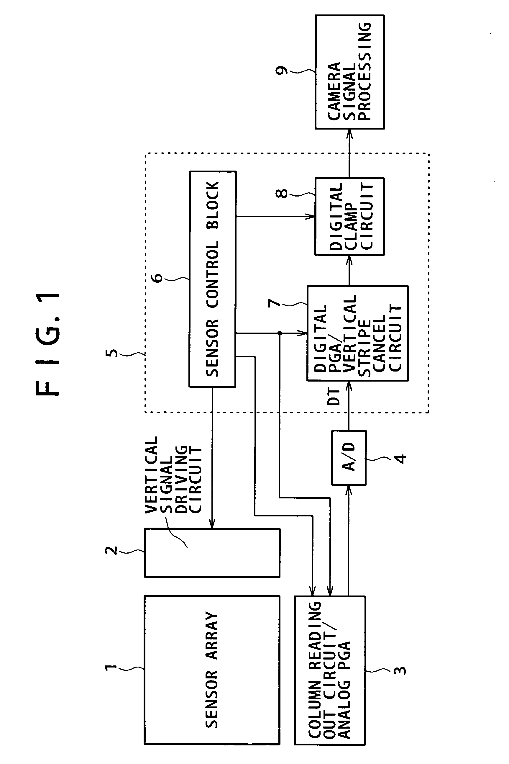
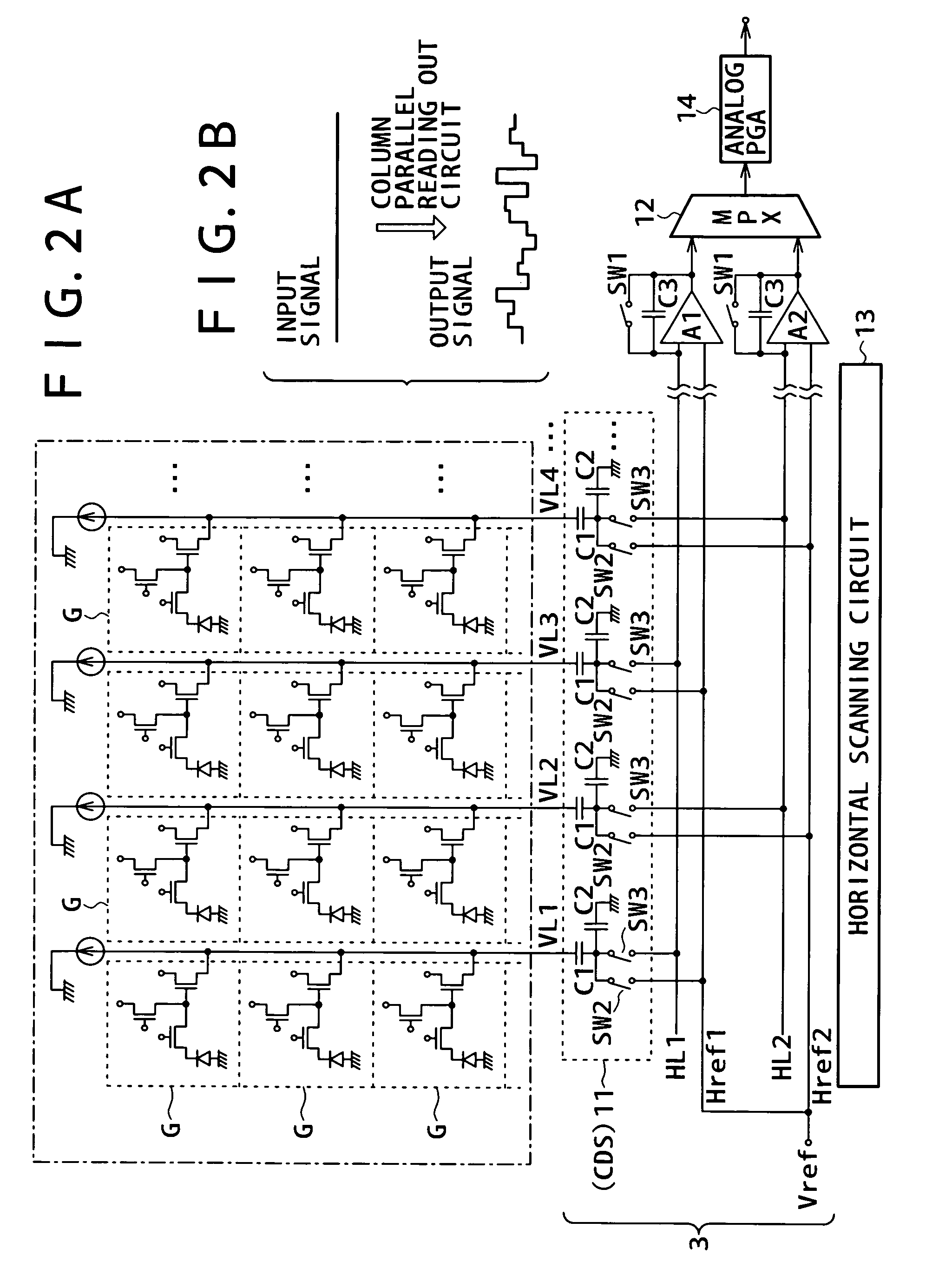
[0078]FIG. 3 shows a configuration of the digital PGA / vertical stripe cancel circuit 7 of a solid-state image pickup apparatus according to a first embodiment of the present invention. The digital PGA / vertical stripe cancel circuit 7 shown in FIG. 3 is formed as a circuit block which detects and removes fixed pattern noise (vertical stripe noise) arising from a dispersion in parallel processes such as column parallel reading out and parallel horizontal transfer described hereinabove with reference to FIG. 2B.

[0079]FIG. 4 illustrates a timing chart of the digital PGA / vertical stripe cancel circuit 7 shown in FIG. 3 within one frame.

[0080] Referring to FIG. 3, a pickup image signal DTin inputted to the digital PGA / vertical stripe cancel circuit 7 is the pickup image signals DT successively supplied from the A / D converter 4 described hereinabove with reference to FIG. 1 to the digital PGA / vertical stripe cancel circuit 7. Meanwhile, a pickup image signal DTout outputted from the digi...

second embodiment

[0114] In the process according to the first embodiment described above, to raise the averaging accuracy, it is necessary to provide the vertical stripe detection period T2 as a period for a number of rows as great as possible within one frame. However, as the number of lines increases within the vertical stripe detection period T2, this suppresses the operation frequency or frame rate and is not preferable.

[0115] Therefore, the invalid pixel period for vertical stripe detection within one frame cannot be increased very much. Consequently, under certain circumstances, the accuracy in addition average is not sometimes assured sufficiently.

[0116] Therefore, the second embodiment implements a configuration which can assure the accuracy in arithmetic averaging without the necessity for a long invalid pixel period for vertical stripe detection within one frame.

[0117]FIG. 5 shows a configuration of the digital PGA / vertical stripe cancel circuit 7 of the solid-state image pickup apparat...

third embodiment

[0155] The third embodiment relates to arrangement of the digital PGA 20 in the digital PGA / vertical stripe cancel circuit 7.

[0156]FIGS. 7A, 7B and 7C show a circuit portion of the solid-state image pickup apparatus including the analog PGA 14, A / D converter 4 and digital PGA / vertical stripe cancel circuit 7 in a simplified form. As a block corresponding to the digital PGA / vertical stripe cancel circuit 7, the digital PGA 20 and the correction processing system (average arithmetic operation circuit 31, subtractor 32, adder 33, RAM 34, divider 35 and subtractor 37). Although the selector 38 and so forth are omitted in FIGS. 7A, 7B and 7C, it should be recognized that the processing system shown in FIG. 3 or 5 is shown schematically.

[0157] Particularly for the convenience of description below, the average arithmetic operation circuit 31, subtractor 32, adder 33 and RAM 34 are collectively referred to as detection section DTC. Meanwhile, the divider 35 and subtractor 37 are collectiv...


PUM


Abstract

A solid-state image pickup apparatus and an image pickup method are disclosed which can detect and correct fixed pattern noise efficiently and accurately. Pickup image signals produced by reading out signals in parallel from a pixel sensor section are subject to an analog gain process, an A/D conversion process and a digital gain process. Within a period within which the pickup image signals which are based on a fixed value are inputted within a one-frame period, a reference signal average is produced from the signals. Sum values of difference values of the signals from the reference signal average are stored. Within a period within which the pickup image signals from valid pixels are inputted within the one-frame period, fixed pattern noise is removed from the pickup image signals using division averages obtained by dividing the stored sum values.

Description

BACKGROUND OF THE INVENTION [0001] This invention relates to a solid-state image pickup apparatus and an image pickup method for a solid-state image pickup apparatus, and more particularly to correction of fixed pattern noise for a solid-state image pickup apparatus and an image pickup method for a solid-state image pickup apparatus. [0002] An image pickup apparatus which uses a solid-state image pickup element such as a CMOS image sensor is known already and is still developed and investigated in order to achieve further increase in number of pixels, speed in image pickup, a wide dynamic range and further reduction of noise. [0003] However, if the processing frequency is raised simply in order to process a greater number of pixels at a higher speed, then this gives rises to a problem of degradation of an analog circuit system in terms of noise, power consumption and accuracy. Therefore, such a technique is used as to read out, from an image pickup element array in which solid-state...

Claims


Application Information

Patent Timeline
Patent Type & Authority Applications(United States)
IPC IPC(8): H04N5/228H04N5/335H04N5/345H04N5/365H04N5/369H04N5/374H04N5/378
CPCH04N5/361H04N5/378H04N5/3658H04N25/677H04N25/63H04N25/75H04N25/67
Inventor HISAMATSU, YASUAKIHARUTA, TSUTOMUMATSUMOTO, KEN
Owner SONY CORP
Why Eureka
Try Eureka