Collimating detection apparatus and optical module packaging apparatus using the same

Inactive Publication Date: 2005-06-30
ELECTRONICS & TELECOMM RES INST
View PDF1 Cites 10 Cited by
  • Summary
  • Abstract
  • Description
  • Claims
  • Application Information

AI Technical Summary

Benefits of technology

[0019] The present invention is contrived to address the foregoing problems. According to a preferred embodiment of the present invention, a lens position where a beam emitted from a collimating lens is converted into parallel light can be found with an automated optical alignment method, and

Problems solved by technology

Further, an optical feedback that gives a bad effect on the stabilized single mode operation of the laser diode must be blocked.
Further, unfortunately, if the optical axis of the optical fiber ferrule 11 and the submodule 50 are unmatched, the coupling efficiency of the light focused onto the optical fiber 23 is degraded.
In the conventional aligning method, a first problem is that the alignment of the right and left of the laser submodule 50 is conducted by the microscope, however, it depends on the determination of an operator who makes an observation through the microscope, so that the accuracy cannot exceed the limit of the human perception.
Secondly, in aligning the top and bottom of the laser su

Method used


Image

  • Collimating detection apparatus and optical module packaging apparatus using the same
  • Collimating detection apparatus and optical module packaging apparatus using the same
  • Collimating detection apparatus and optical module packaging apparatus using the same

Examples


Example

[0027] The present invention will now be described more fully hereinafter with reference to the accompanying drawings, in which preferred embodiments of the invention are shown. This invention may, however, be embodied in different forms and should not be construed as limited to the embodiments set forth herein. Rather, these embodiments are provided so that this disclosure will be thorough and complete, and will fully convey the scope of the invention to those skilled in the art.

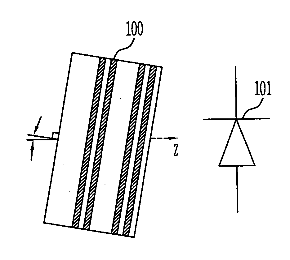
[0028]FIG. 3 is a schematic configuration diagram of a collimating detection apparatus according to an embodiment of the present invention.

[0029] Referring to FIG. 3, the collimating detection apparatus according to an embodiment of the present invention is composed of a Fabry-Perot etalon 100 and a light detector 101.

[0030] As an incident angle of the light emitted from a laser diode (not shown) is changed, the Fabry-Perot etalon 100 changes the optical power of the output light, which allows determinin...


PUM


Abstract

Provided is a collimating detection device for use in fabricating a semiconductor laser diode module, wherein the collimating detection apparatus discriminates using a light output difference between a case where the beam emitted from a laser diode becomes parallel light through a collimating lens and a case where the parallel light is not made, using properties of Fabry-Perot etalon that changes optical power of the output beam as an angle of an incident beam is changed.

Description

BACKGROUND [0001] 1. Field of the Invention [0002] The present invention relates to a collimating detection apparatus and an optical module packaging apparatus using the same, wherein the collimating detection apparatus discriminates a light output difference between a case where the beam emitted from a laser diode becomes parallel light through a collimating lens and a case where the parallel light is not made, using a feature of a Fabry-Perot etalon that changes optical power of the output beam as an angle of the incident beam is changed. That is, the present invention relates to an alignment apparatus for aligning and attaching the collimating lens mounted on a laser diode submodule to an exact place, in fabricating a semiconductor laser diode module for high-speed optical communication with an optical fiber. [0003] 2. Discussion of Related Art [0004] Generally, factors that should be considered in packaging a semiconductor laser diode module used for high-speed optical communica...

Claims


Application Information

Patent Timeline
IPC IPC(8): G02B6/42
CPCG02B6/422G02B6/4206G02B6/42
Inventor LEE, SANG KYUNOH, HEANG SUKKOH, JAI SANG
Owner ELECTRONICS & TELECOMM RES INST
Why Eureka
Try Eureka