
Storage system

Inactive Publication Date: 2005-06-30
HITACHI LTD
View PDF99 Cites 19 Cited by
  • Summary
  • Abstract
  • Description
  • Claims
  • Application Information

AI Technical Summary

Benefits of technology

[0013] Hence an object of this invention is to increase the power that can be supplied to the HDD units installed in a storage system.
[0017] A storage system according to another aspect of the invention disclosed in this application comprises a plurality of physical storage devices (for example, hard disk drives), and a power supply circuit which outputs power at a prescribed voltage level. Power conversion circuits are provided for each of the physical storage devices, and each power conversion circuit converts power at the prescribed voltage level from the power supply circuit into power at the voltage levels required by the corresponding physical storage devices, and provides the power to the physical storage devices. By selecting the output voltage level of the power conversion circuit for each physical storage device, a plurality of types of physical storage devices having different voltage specifications can be installed in the same storage system. It is desirable that the voltage level output by the power supply circuit be a single level equal to or greater than the highest level among the power supply voltage levels required by the plurality of physical storage devices. When the internal circuit components of a certain physical storage device require a plurality of types of power at different voltage levels, the power conversion circuit for that physical storage device may output all the plurality of types of power at the different voltage levels, or may output a single type of power at the highest voltage level (or at a voltage level higher than the highest voltage level) among the plurality of types of power. In the latter case, it is necessary to perform power conversion within the physical storage device of the voltage level from the power conversion circuit to the lower voltage levels required by the internal circuit components. However, because the voltage applied to the physical storage device is higher, the current flowing to the power supply terminals in the connector of the physical storage device is smaller, and so the power which can be supplied within the range of allowable currents of the power supply terminals is increased. Further, when one type of power is supplied to a physical storage device from a power conversion circuit, if the connector of the physical storage device has a plurality of power supply terminals, all of the plurality of power supply terminals can be used for the supply of the one type of power. As a result, higher power can easily be supplied within the range of allowable currents of the power supply terminals.
[0028] By means of one embodiment of this invention, the power which can be supplied to the HDD units installed in a storage system can be increased.

Problems solved by technology

Further, as magnetic disks move toward higher densities, faster data transfer rates and higher revolution rates, there is a trend toward increased power consumption within HDD units.
However, as explained above, there is a tendency toward increases in the power consumption of HDD units, and so there is the possibility that it will no longer be possible to supply adequate power to HDD units using existing power supply terminals.

Method used


Image

  • Storage system
  • Storage system
  • Storage system

Examples


Embodiment Construction

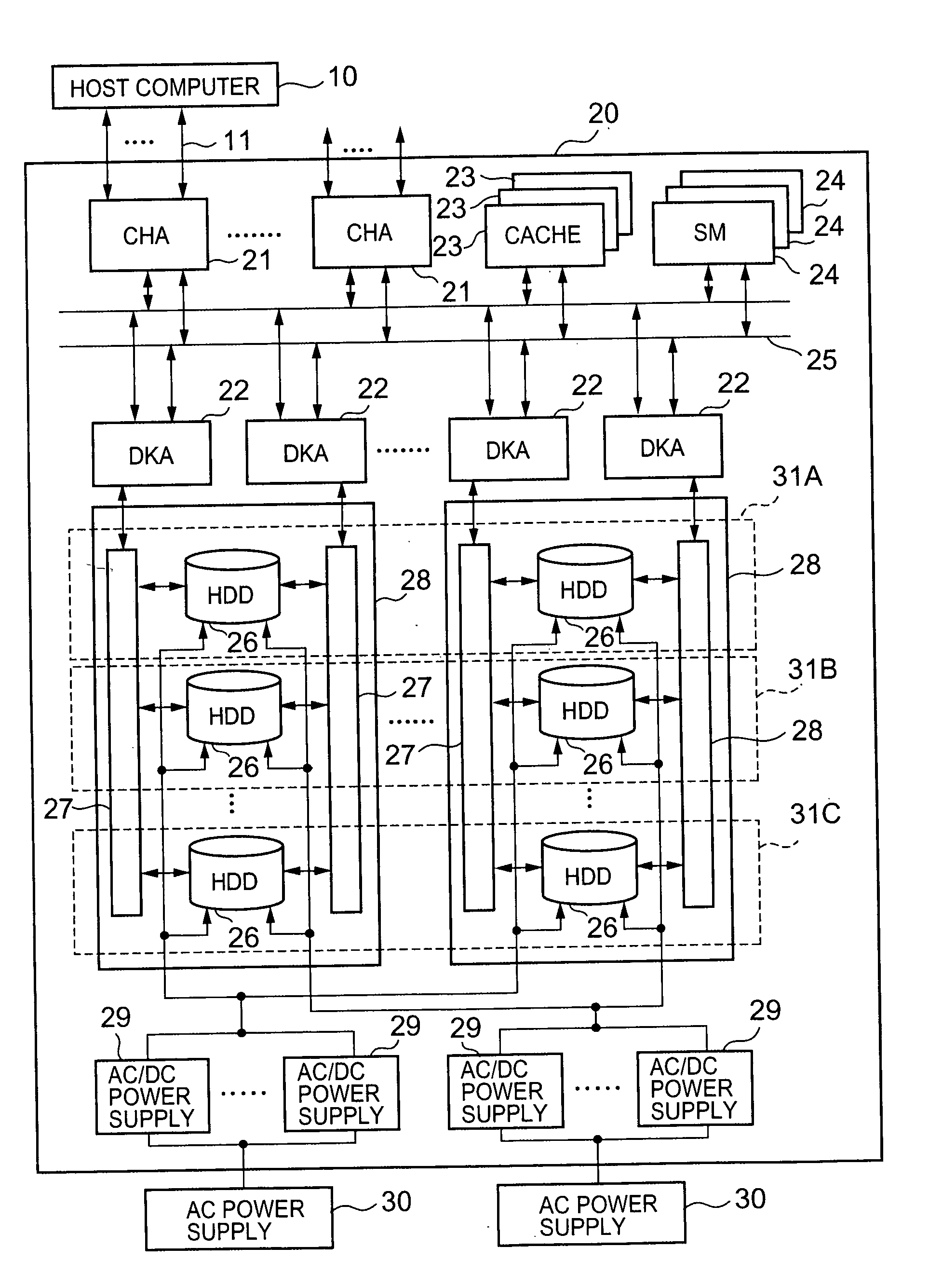
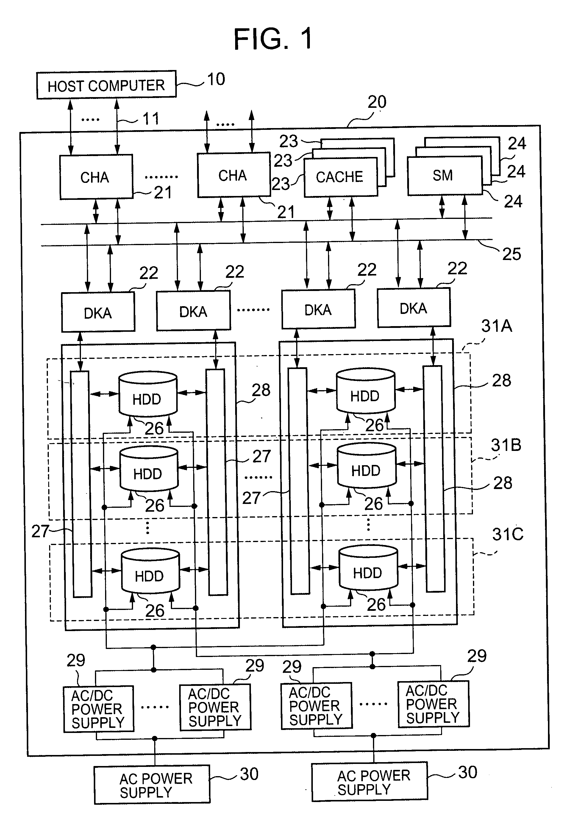
[0043]FIG. 1 shows in summary the overall configuration of one aspect of a storage system according to this invention.

[0044] The storage system 20 shown in FIG. 1 comprises one or more channel adapters (CHA) 21, one or more disk adapters (DKA) 22, one or more cache memories (CACHE) 23, one or more shared memories (SM) 24, one or more common paths 25, a plurality of physical storage devices (that is, storage apparatus) 26, one or more connection control circuits 27, one or more motherboards 28, and one or more main power supply devices 29. As the physical storage devices 26, hard disk drives, nonvolatile semiconductor memory, or other types of devices can be employed, but typically hard disk drives (hereafter abbreviated “HDDs”) are used. In the following explanation also, it is assumed that HDDs are employed.

[0045] The channel adapter 21, disk adapter 22, cache memory 23 and shared memory 24 are interconnected by the common path 25. The common path 25 may be made twofold redundant...


PUM


Abstract

In a RAID system, the power supplied to hard disks (HDDs) can be increased, and a plurality of types of HDDs can be installed. A plurality of HDD packs 33 are supplied with a single high voltage from a motherboard 28. The HDD packs 33 each accommodate, in a canister, an HDD 107, 181, 185 or 187 with different power supply specifications or communication interface specifications, as well as a DC / DC converter 109 to convert the power supply. Part of the HDD packs 33 have a data transfer interface conversion circuit 195 as well.

Description

CROSS-REFERENCE TO RELATED APPLICATIONS [0001] This application relates to and claims priority from Japanese Patent Application No. 2003-428829 filed on Dec. 25, 2003, the entire disclosure of which is incorporated herein by reference. BACKGROUND OF THE INVENTION [0002] 1. Field of the Invention [0003] This invention relates to a storage system having a plurality of physical storage devices (for example, hard disk drives), and in particular to technology to provide a power supply to a plurality of storage devices. [0004] 2. Description of the Related Art [0005] Storage systems of which RAID systems are representative comprise numerous storage devices, such as for example hard disk drives (hereafter abbreviated “HDD”). In Japanese Patent Laid-open 4-78062, a RAID system configured to supply power to a plurality of HDDs from the same power supply circuit is described. [0006] In general, each of the HDDs installed in such a storage system is assembled as a single unit (hereafter called...

Claims


Application Information

Patent Timeline
IPC IPC(8): G06F1/26G06F3/06G11B33/00G11B33/12H05K5/00
CPCG11B33/126G06F1/26
Inventor SUZUKI, HIROSHIMATSUSHIGE, HIROMIOGAWA, MASATOYOKOYAMA, TOMOKAZUKUROKAWA, MASATERU
Owner HITACHI LTD
Features
  • Generate Ideas
  • Intellectual Property
  • Life Sciences
  • Materials
  • Tech Scout
  • Unparalleled Data Quality
  • Higher Quality Content
  • 60% Fewer Hallucinations
Learn More