
Channel time allocation method in WPAN

Inactive Publication Date: 2005-06-30
SAMSUNG ELECTRONICS CO LTD
View PDF31 Cites 100 Cited by
  • Summary
  • Abstract
  • Description
  • Claims
  • Application Information

AI Technical Summary

Benefits of technology

[0016] An aspect of the present invention is to provide a channel time allocation method which can support QoS even when a channel error is introduced in WPAN and support a VBR stream or a high layer reliable protocol without degrading network utilization.

Problems solved by technology

It is noted that Carrier Sense Multiple Access with Collision Avoidance (CSMA / CA) scheme, which is widely used, cannot provide quality of service (QoS) in IEEE 802.15.3x high rate WPAN.
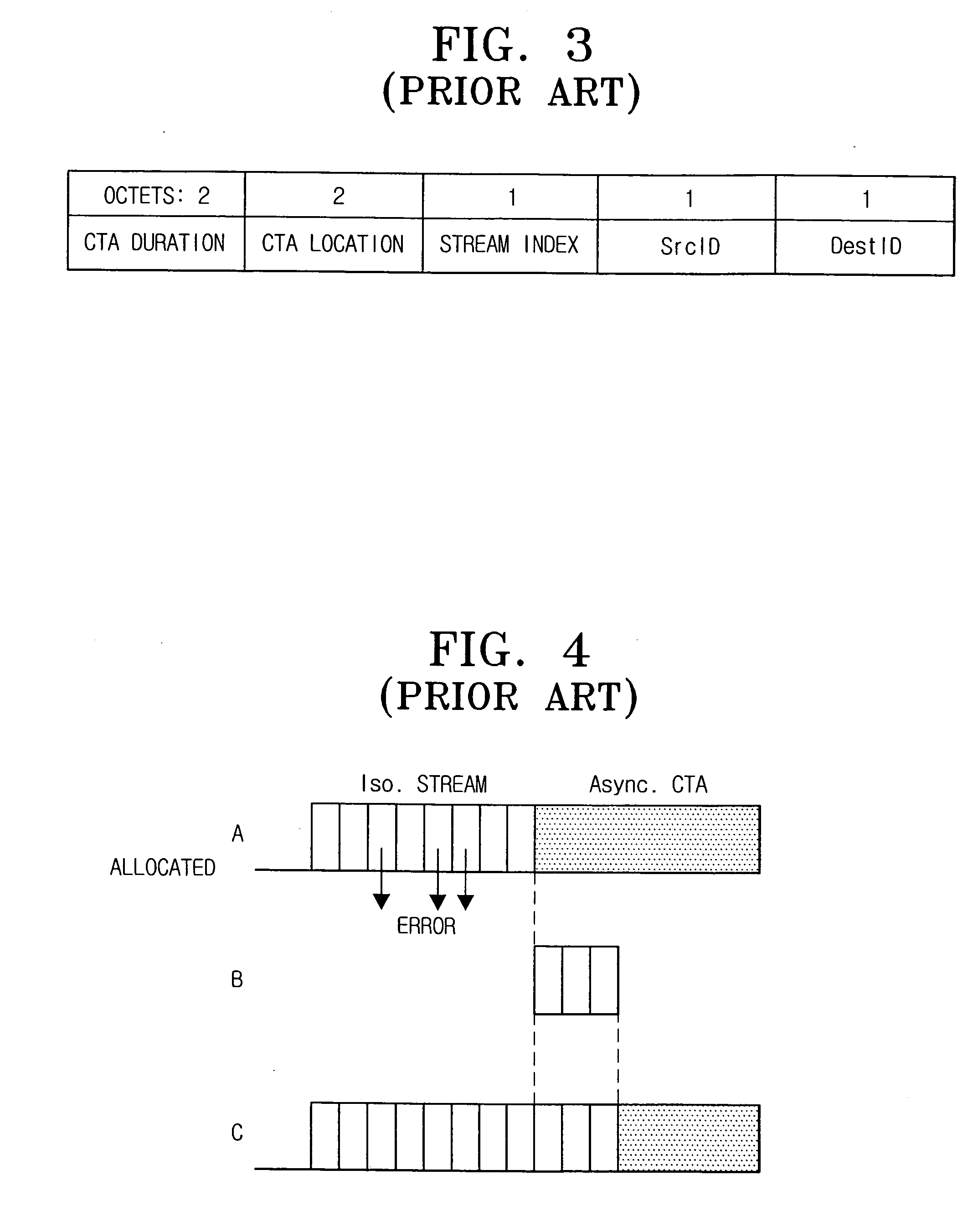
However, according to the conventional channel time allocation method, if channel status deteriorates and a frame error or damage is introduced, a frame to be transmitted is not transmitted completely, thus degrading QoS.
Meanwhile, more channel time would be allocated if additionally required time for the re-transmission due to channel error were to be accurately predicted, but this is not possible in actual practice.
Furthermore, the conventional channel time allocation method cannot support a high layer reliable protocol.
As a result, it is difficult to allocate the channel time in the above case.

Method used


Image

  • Channel time allocation method in WPAN
  • Channel time allocation method in WPAN
  • Channel time allocation method in WPAN

Examples


Embodiment Construction

[0032] Reference will now be made in detail to the embodiments of the present invention, examples of which are illustrated in the accompanying drawing figures, wherein like reference numerals refer to like elements throughout. The embodiments are described below in order to explain the present invention by referring to the drawing figures.

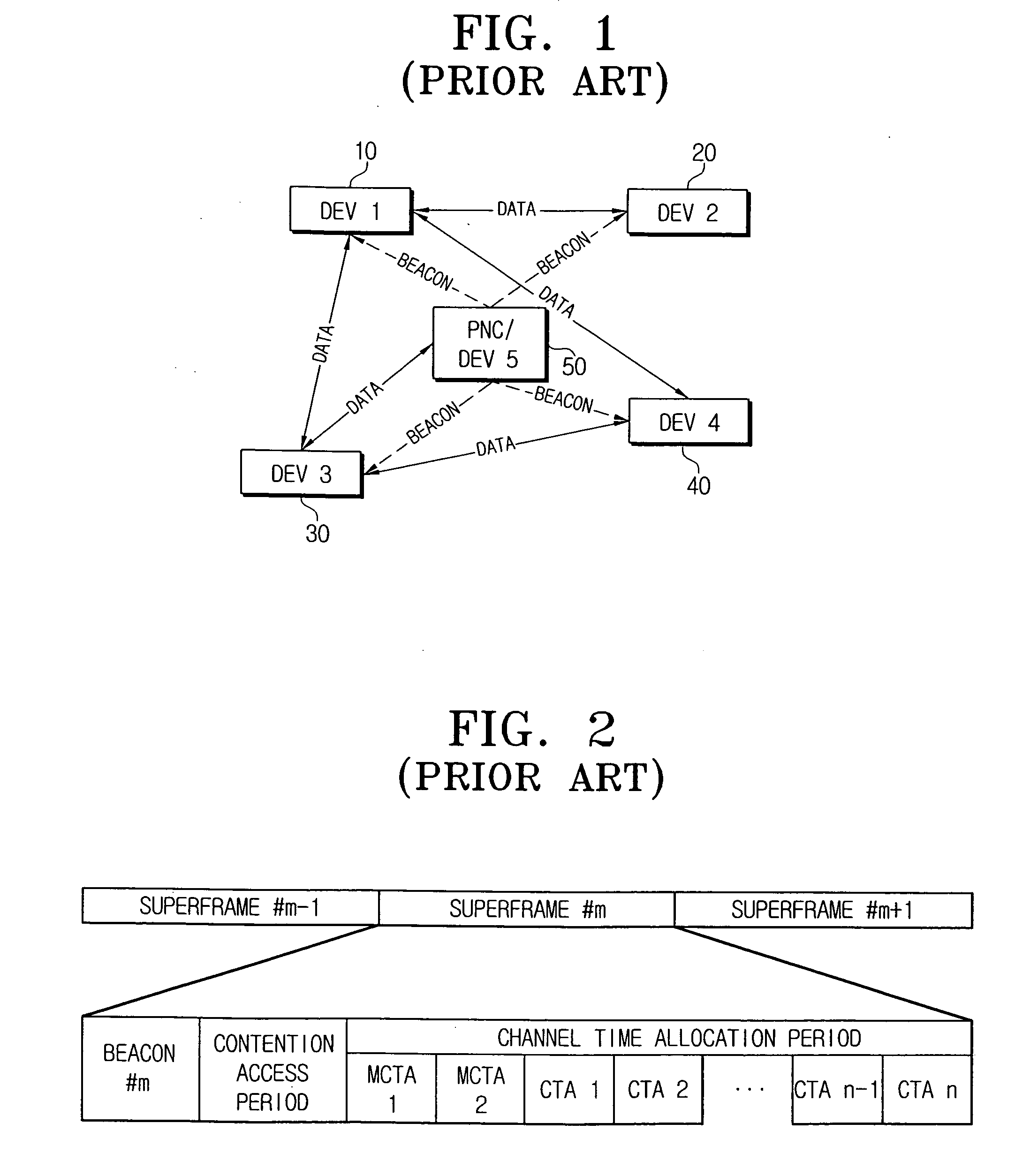
[0033] A channel time allocation method in a wireless personal area network (WPAN) according to an embodiment of the present invention is applied to a WPAN based on the IEEE 802.15.3 standard, but the present invention is not limited to the specifics of this embodiment. The channel time allocation method may be applied to any other wireless network environments appropriate to the teaching herein. Understanding the present invention will be facilitated by referring to FIG. 1 which illustrates the configuration of a conventional WPAN. Elements having the same function and structure as the elements shown in FIG. 1, will be given the same reference nu...


PUM


Abstract

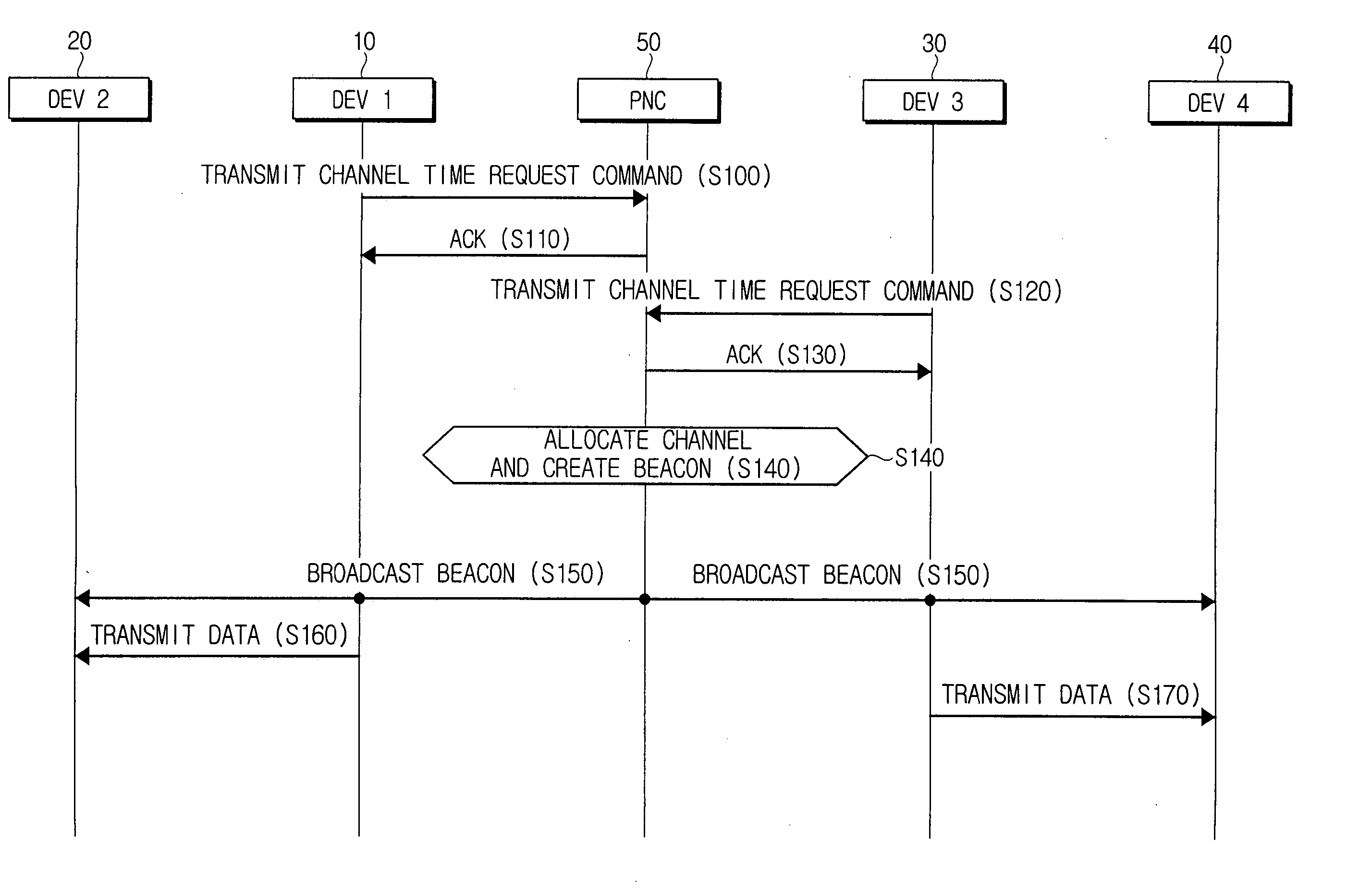
A channel time allocation method in a wireless network which is synchronized by a synchronization signal broadcasted from a coordinator, includes a plurality of data devices linked to the wireless network each transmitting to the coordinator a command requesting a first channel time necessarily required and a second channel time selectively required according to a type of data to be transmitted, the coordinator allocating a channel time which includes a channel time allocation (CTA) period corresponding to each first channel time requested by the plurality of the devices, and a shared CTA period corresponding to each second channel time requested by the plurality of the devices and to be shared and used by the plurality of the devices, and broadcasting to the plurality of the devices the synchronization signal to which information of the allocated channel time is inserted.

Description

CROSS-REFERENCE TO RELATED APPLICATIONS [0001] This application claims the benefit under 35 U.S.C. § 119(a) from Korean Patent Application No. 2003-99745, filed Dec. 30, 2003 in the Korean Intellectual Property Office, the disclosure of which is incorporated herein by reference in its entirety. BACKGROUND OF THE INVENTION [0002] 1. Field of The Invention [0003] The present invention relates generally to a channel time allocation method. More particularly, the present invention pertains to a channel time allocation method which can provide quality of service (QoS) when a channel error occurs, and efficiently support a variable bit rate such as MPEG-2 video. [0004] 2. Description of The Related Art [0005] In contrast to a Local Area Network (LAN) or a Wide Area Network (WAN), a Personal Area Network (PAN) is a network owned by an individual person. Devices owned by the individual person are interconnected to construct the network to provide convenience for the owner. The wireless impl...

Claims


Application Information

Patent Timeline
IPC IPC(8): H04J3/16H04L29/08H04L12/28H04W72/04H04W74/04H04W84/10H04W84/12H04W84/20
CPCH04J3/1682H04W56/00H04W72/0446H04W72/042H04W72/0413H04W72/21H04W72/23H04W72/04H04W84/18
Inventor YOON, WON-YONGKIM, YONG-SUK
Owner SAMSUNG ELECTRONICS CO LTD
Learn More