Resource allocation in mobile network

Inactive Publication Date: 2005-06-30
NOKIA CORP
View PDF5 Cites 33 Cited by
  • Summary
  • Abstract
  • Description
  • Claims
  • Application Information

AI Technical Summary

Benefits of technology

[0006] The object of the present invention is to provide an improved method and apparatus for allocating resources in a radio network. According to one embodiment, the invention provides a resource allocation method in a mobile network using time division multiple access, the method comprising steps of collecting information on inter-cell handovers in the mobile network, main

Problems solved by technology

The success of prior art slot allocation methods is to an excessiv

Method used


Image

  • Resource allocation in mobile network
  • Resource allocation in mobile network
  • Resource allocation in mobile network

Examples


Embodiment Construction

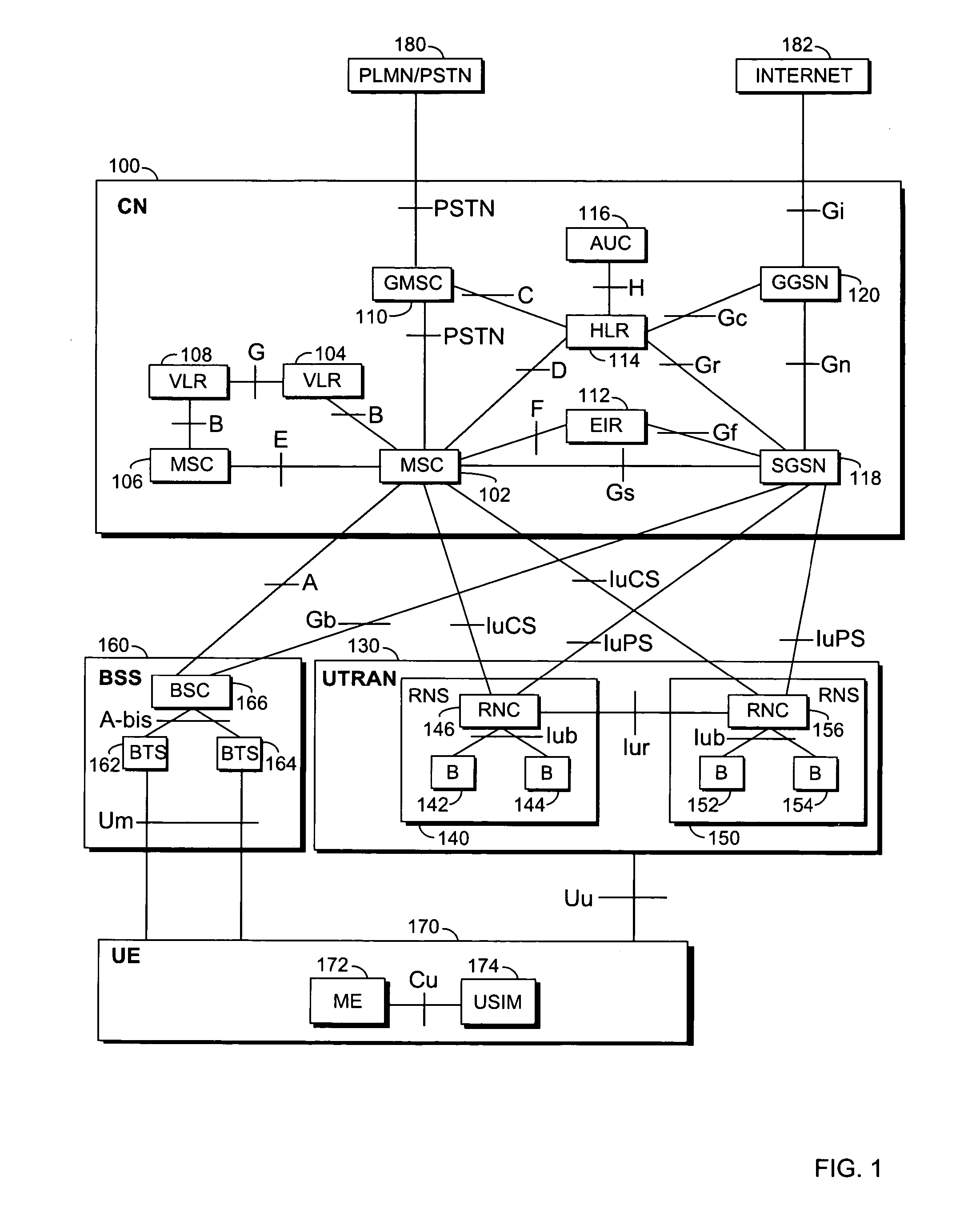
[0017]FIG. 1 is a simplified block diagram showing the most important parts of a radio system at network element level and the interfaces between the network elements. The example of FIG. 1 illustrates a radio network comprising parts of a 2 / 2.5-generation GSM (Global System for Mobile communication) and 3.generation UMTS (Universal Mobile Telephony System) networks. Besides the network shown in FIG. 1, the invention can also be used in other radio networks employing TDMA or TD-CDMA. One example of such a network is the Chinese TD-SCDMA (Time Division Synchronized CDMA), which is based on the 3GPP UTRA TDD with narrowband carriers.

[0018] In FIG. 1, the structure and functions of the network elements are not described in detail since they are generally known. The main parts of the shown radio system include a core network (CN) 100, a radio access network (UTRAN) 130 and a user equipment (UE) 170. Radio access network UTRAN 130 belongs to the third generation and is implemented by th...


PUM


Abstract

A mobile network using time division multiple access, the network comprising means for collecting information on inter-cell handovers in the mobile network, means for maintaining a network topology on the basis of the collected inter-cell handover information, the network topology dynamically defining one or more neighboring cells for a given cell and means for allocating, at the given cell, to a mobile terminal a time slot on the basis of load situation in the neighboring cells defined by the dynamically maintained network topology.

Description

FIELD [0001] The invention relates to allocation of radio resources in a mobile network. BACKGROUND [0002] In a cellular radio system using Time Division Multiple Access (TDMA), when allocating a radio resource to a user equipment (UE), the network has to consider as one allocation parameter the time slot that shall be allocated to the UE. For instance, in 3GPP UTRA (Universal Mobile Telephony System Terrestrial Radio Access) TDD (Time Division Duplex) using both TDMA and Code Division Multiple Access (CDMA), several UEs separated by a spreading code can utilize the same time slot. Besides the load in the same cell using the same time slot, the level of noise experienced by a UE depends also on the degree of utilization of the corresponding slot in neighbouring cells. So careful design of the slot allocation strategy in Base Transceiver Stations (BTS) plays an important role in distributing the traffic to all the slots optimally. [0003] In determining which timeslot to allocate to a...

Claims


Application Information

Patent Timeline
IPC IPC(8): H04W16/06H04W36/08
CPCH04W24/00H04W24/08H04W72/0486H04W72/0446H04W36/08H04W72/52
Inventor ZHU, YUAN
Owner NOKIA CORP
Why Eureka
Try Eureka