Thrust dynamic pressure bearing, spindle motor using the same, and information recording and reproducing apparatus using them

a dynamic pressure bearing and spindle motor technology, applied in the field of thrust, can solve the problems inability to ensure a sufficient radial bearing length, and inability to achieve the effect of lubricating oil leakage, enhancing reliability and durability, and stable bearing performan

Inactive Publication Date: 2005-06-30
PANASONIC CORP
View PDF5 Cites 10 Cited by
  • Summary
  • Abstract
  • Description
  • Claims
  • Application Information

AI Technical Summary

Benefits of technology

[0024] According to these structures, an information recording and reproducing apparatus of high reliability and durability, being free from contamination due to lubricating oil leak, is realized.
[0025] Therefore, in the thrust dynamic pressure bearing of the invention, only by adding a simple auxiliary groove, bubbles mixing into the lubricating oil can be discharged securely without allowing to stay within the bearing, and lubricating oil due to bubbles can be prevented, and hence stable bearing performance is obtained, and the bearing is also enhanced in reliability and durability.
[0026] Also by using such thrust bearing, bubbles mixing the bearing can be discharged securely only by adding a simple auxiliary groove, a spindle motor of high reliability and durability is realized, and a spindle motor of small size and thin type is realized, and by mounting such spindle motor, an information recording and reproducing apparatus having high reliability and durability can be realized, and the apparatus can be reduced in size and thickness at the same time.

Problems solved by technology

It is hence suited as thrust dynamic pressure bearing of thin type spindle motor difficult to assure a sufficient radial bearing length.
In such negative pressure, bubbles are likely to be formed in the fluid, and these bubbles are believed to induce decline of bearing performance, in particular, performance decline of thrust dynamic pressure bearing.
Thus, when bubbles are present in the bearing, the bubbles rotate without synchronism with the rotation of rotor, and the bearing rigidity fluctuates during rotation, and deflection not synchronous with rotation is generated, and stable rotary motion of shaft is spoiled, and further if bubbles are stagnant in inner periphery of bearing, when exposed to reduced pressure environment or high temperature environment, bubbles expand and force out the lubricating oil to outside of the bearing to lead to lubricating oil leak, or leaking lubricating oil stains the outer parts of the bearing, and hence various methods have been proposed for removing bubbles generated or staying in the bearing parts (for example, see Japanese Laid-open Patent No. 2004-112874, Japanese Laid-open Patent No. 2004-132535, Japanese Laid-open Patent No. 2004-183768, etc.).
Further, for the purposes of forming radiant grooves separately in the thrust dynamic pressure generating parts of spiral type, partly extending plural dynamic pressure generating grooves, or expanding the width dimension in the peripheral direction, it requires an extra area of circular plane for forming thrust dynamic pressure generating parts, or the bearing parts are increased in size, and it hard to be used in small size applications.
To realize these proposals without increasing the area of circular plane for forming thrust dynamic pressure generating parts, the area of the portion for forming thrust dynamic pressure generating parts of spiral type must be reduced, but the generating dynamic pressure is decreased in this case, and the operation as thrust bearing is difficult, and serious quality troubles may occur, and these are important problems to be solved.

Method used


Image

  • Thrust dynamic pressure bearing, spindle motor using the same, and information recording and reproducing apparatus using them
  • Thrust dynamic pressure bearing, spindle motor using the same, and information recording and reproducing apparatus using them
  • Thrust dynamic pressure bearing, spindle motor using the same, and information recording and reproducing apparatus using them

Examples


embodiment 1

Preferred Embodiment 1

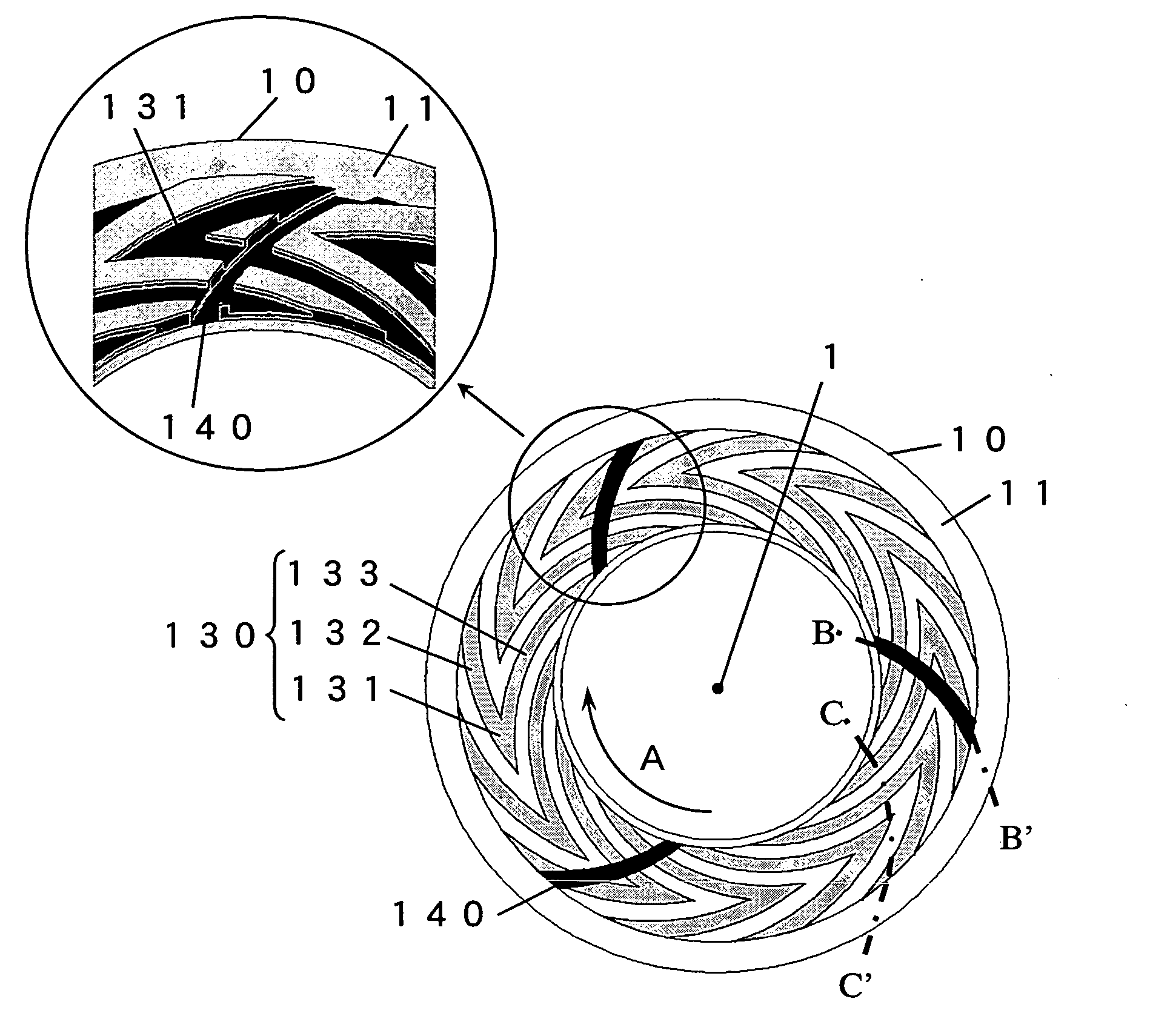
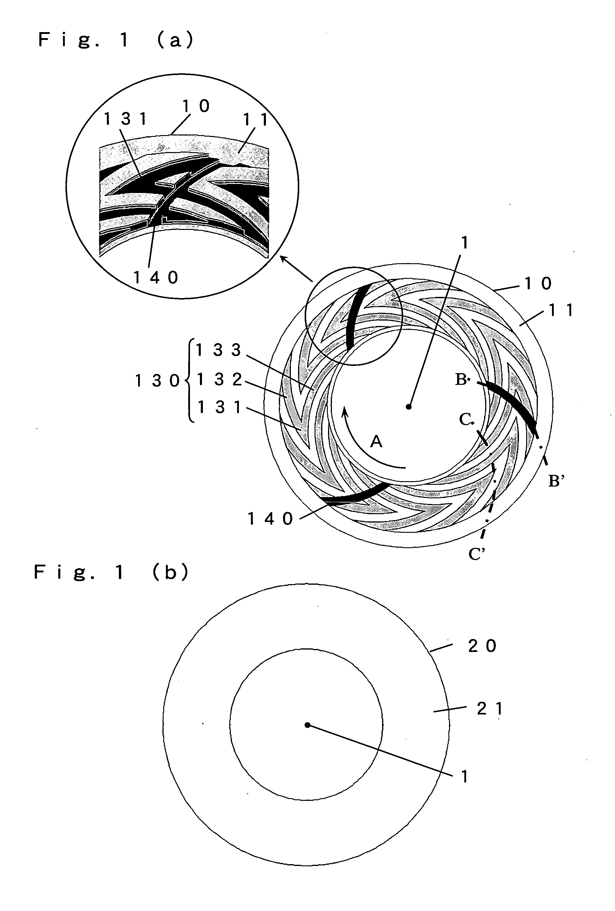
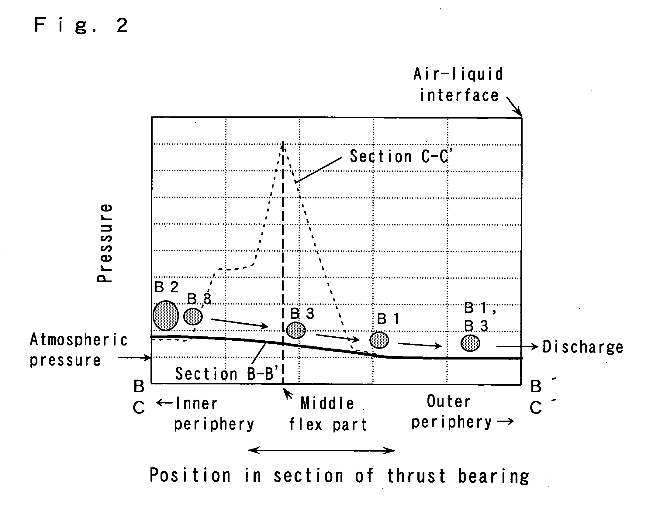
[0053] A thrust dynamic pressure bearing in preferred embodiment 1 of the invention is explained by referring to FIG. 1 to FIG. 5. FIG. 1 (a) is a schematic diagram of bearing surface of rotary side member of thrust dynamic pressure bearing in preferred embodiment 1 of the invention, FIG. 1 (b) is a schematic diagram of bearing surface of fixed side member of thrust dynamic pressure bearing in preferred embodiment 1 of the invention, FIG. 2 is a pressure distribution diagram of bearing section of thrust dynamic pressure bearing in preferred embodiment 1 of the invention, FIG. 3 is a pressure distribution diagram of auxiliary groove section of thrust dynamic pressure bearing in preferred embodiment 1 of the invention, showing the depth of auxiliary groove as parameter, FIG. 4 (a) is a structural diagram of dynamic pressure generating grooves and auxiliary groove provided on bearing surface of bearing rotary side member of thrust dynamic pressure bearing in prefe...

embodiment 2

Preferred Embodiment 2

[0070] A thrust dynamic pressure bearing in preferred embodiment 2 of the invention is explained by referring to FIG. 6 to FIG. 8. FIG. 6 (a) is a bearing surface diagram of rotary side member of thrust dynamic pressure bearing in preferred embodiment 2 of the invention, FIG. 6 (b) is a schematic diagram of bearing surface of fixed side member of thrust dynamic pressure bearing in preferred embodiment 2 of the invention, FIG. 7 (a) is a structural diagram of forming dynamic pressure generating grooves on bearing surface of bearing rotary side member, and forming an auxiliary groove on bearing surface of bearing fixed side member of thrust dynamic pressure bearing in preferred embodiment 2 of the invention, FIG. 7 (b) is a structural diagram of forming an auxiliary groove on bearing surface of bearing rotary side member, and forming dynamic pressure generating grooves on bearing surface of bearing fixed side member of thrust dynamic pressure bearing in preferred...

embodiment 3

Preferred Embodiment 3

[0079] A spindle motor and an information recording and reproducing apparatus using a thrust dynamic pressure bearing are explained in preferred embodiment 3 of the invention by referring to FIG. 9 to FIG. 13. FIG. 9 is a schematic sectional view of principal parts of spindle motor and information recording and reproducing apparatus using thrust dynamic pressure bearing in preferred embodiment 3 of the invention, FIG. 10 is a magnified sectional view of dynamic pressure bearing of spindle motor in preferred embodiment 3 of the invention, FIG. 11 is a perspective view of structure of fixed side bearing surface of dynamic pressure bearing of spindle motor in preferred embodiment 3 of the invention, FIG. 12 is a pressure distribution diagram in radial direction of thrust dynamic pressure bearing and axial direction of radial dynamic pressure bearing of thrust motor in preferred embodiment 3 of the invention, and FIG. 13 is a schematic sectional view showing other ...


PUM

PropertyMeasurementUnit
dynamic pressureaaaaaaaaaa
pressureaaaaaaaaaa
depthaaaaaaaaaa

Abstract

In order to prevent lubricating oil leak due to bubbles in thrust dynamic pressure bearing of herringbone grooves, stabilize the bearing performance, and enhance the reliability and durability, auxiliary grooves deeper than pump-in type herringbone grooves for generating dynamic pressure are provided, and the bearing inner periphery and bearing outer periphery are linked by a pressure gradient descending slowly, and therefore bubbles present in bearing inner periphery can be guided into the bearing outer periphery through auxiliary grooves, and discharged to outside of the bearing from the air-liquid interface, so that lubricating oil leak due to bubbles can be prevented.

Description

FIELD OF THE INVENTION [0001] The present invention relates to a thrust type dynamic pressure bearing for supporting the load in the axial direction in a rotary machine rotating smoothly at high speed, and more particularly to a thrust dynamic pressure bearing capable of eliminating bubbles mixing in a lubricating oil easily without allowing to stay in the bearing, a spindle motor using it, and an information recording and reproducing apparatus using them. BACKGROUND OF THE INVENTION [0002] In a spindle motor for rotating recording media of information recording and reproducing apparatus such as hard disk drive, as means for supporting the load in the axial direction of rotor and suppressing deflection of rotor rotation, various thrust type dynamic pressure bearings are proposed, which are designed to generate dynamic pressure by herringbone grooves having middle flex part (for example, see Japanese Patent Registration No. 3155529). [0003] Referring first to FIG. 14 and FIG. 15, the...

Claims


Application Information

Patent Timeline
Patent Type & Authority Applications(United States)
IPC IPC(8): F16C17/04F16C33/10G11B19/20
CPCF16C17/04F16C17/045F16C2370/12F16C33/107G11B19/2009F16C17/107
Inventor KITA, HIROMIOBATA, SHIGEOMIYAMORI, KENICHINODA, HIROMITSU
Owner PANASONIC CORP
Why Eureka
Try Eureka