Microring and microdisk resonators for lasers fabricated on silicon wafers

a micro-disk and laser technology, applied in the direction of optical waveguide light guide, optical element, instruments, etc., can solve the problem that the micro-disk or the micro-ring micro-resonator has not been fabricated on silicon

Inactive Publication Date: 2005-06-30
INTEL CORP +1
View PDF10 Cites 36 Cited by
  • Summary
  • Abstract
  • Description
  • Claims
  • Application Information

AI Technical Summary

Problems solved by technology

To date, a microdisk or a microring microresonator has not been fabricated on silicon to provide light-emitting devices that are compatible with complementary metal-oxide semiconductor (CMOS) processes and that are monolithically fabricated on silicon substrates.

Method used


Image

  • Microring and microdisk resonators for lasers fabricated on silicon wafers
  • Microring and microdisk resonators for lasers fabricated on silicon wafers
  • Microring and microdisk resonators for lasers fabricated on silicon wafers

Examples


Embodiment Construction

[0010] In the following detailed description, numerous specific details are set forth in order to provide a thorough understanding of the invention. However, it will be understood by those skilled in the art that the present invention may be practiced without these specific details. In other instances, well-known methods, procedures, components and circuits have not been described in detail so as not to obscure the present invention.

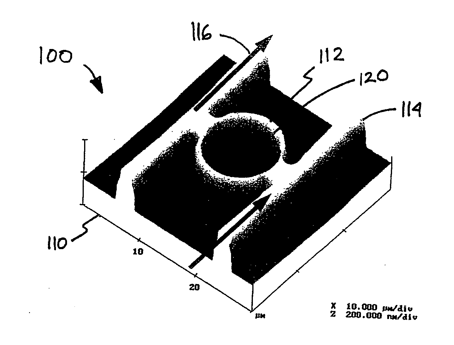
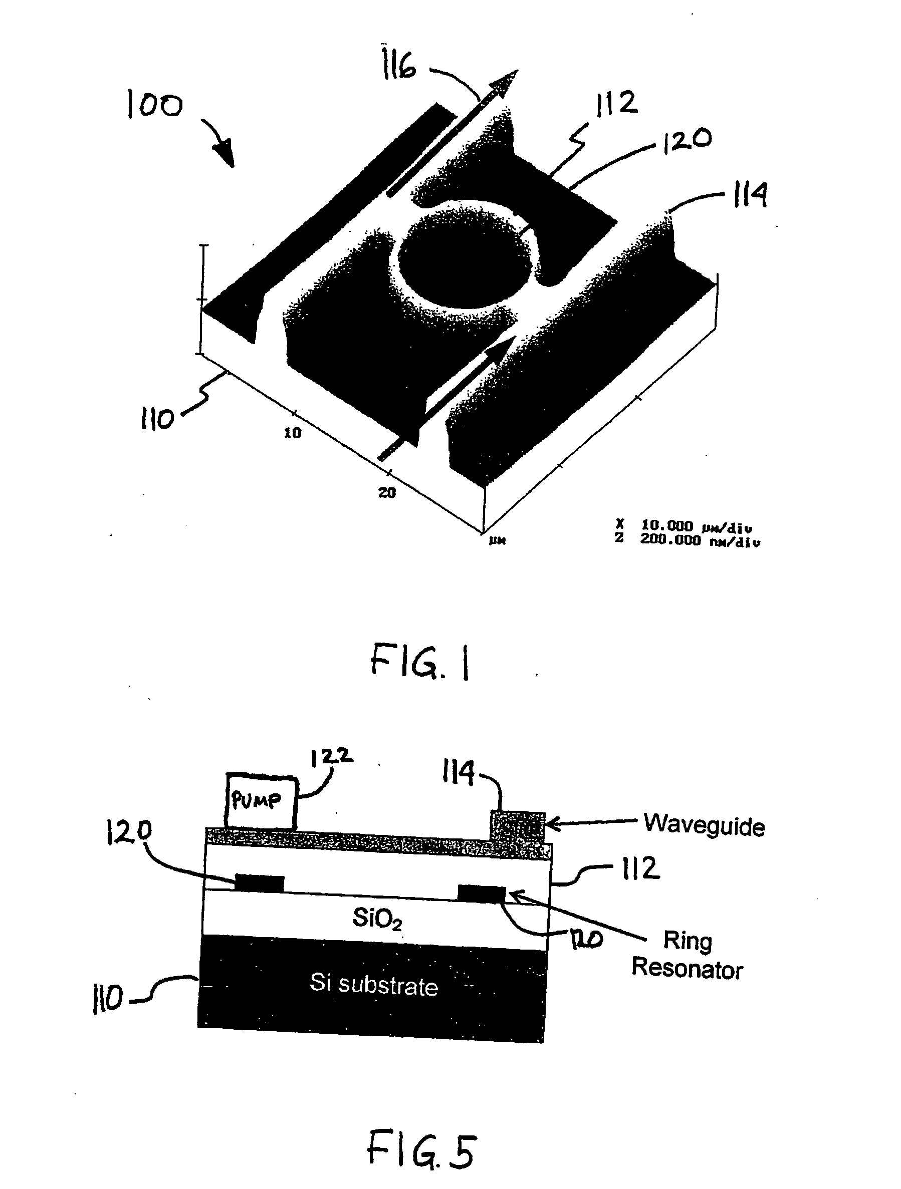
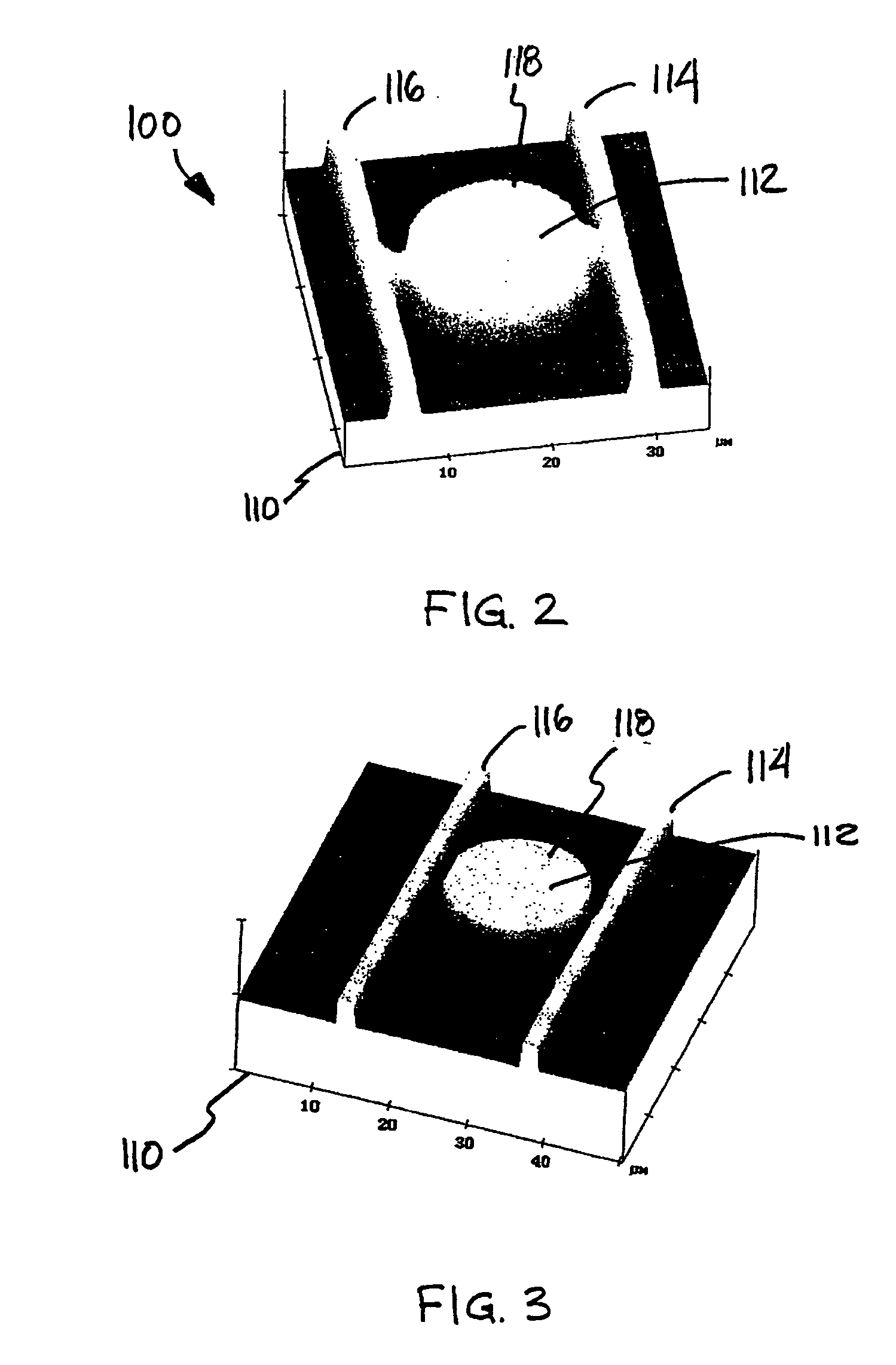
[0011] Referring now to FIG. 1, FIG. 2, and FIG. 3, diagrams of a microresonator disposed between two silicon dioxide (SiO2) waveguides on a silicon substrate in accordance with one embodiment of the present invention will be discussed. In accordance with the present invention, a microresonator may be utilized in or as a device that produces light and may have the potential to generate coherent light such as laser light that is useful, for example, for optical communication between integrated circuits with an electronic device such as a computer, althou...


PUM


Abstract

Briefly, in accordance with one embodiment of the invention, a light emitting device may comprise a microresonator having an annular structure such as a ring or a disk to recirculate light at a desired wavelength formed on a silicon substrate. A waveguide may be disposed on the silicon substrate to couple with the microresonator. The microresonator may be formed with silicon or silicon-germanium nanocrystals in silicon dioxide and rare earths such as erbium or ytterbium. The light emitting device may be monolithically fabricated using a standard silicon process.

Description

BACKGROUND OF THE INVENTION [0001] To date, a microdisk or a microring microresonator has not been fabricated on silicon to provide light-emitting devices that are compatible with complementary metal-oxide semiconductor (CMOS) processes and that are monolithically fabricated on silicon substrates. DESCRIPTION OF THE DRAWING FIGURES [0002] The subject matter regarded as the invention is particularly pointed out and distinctly claimed in the concluding portion of the specification. The invention, however, both as to organization and method of operation, together with objects, features, and advantages thereof, may best be understood by reference to the following detailed description when read with the accompanying drawings in which: [0003]FIG. 1 is a diagram of a microring microresonator disposed between two silicon dioxide waveguides on a silicon substrate in accordance with one embodiment of the present invention; [0004]FIG. 2 is a diagram of a wet etched microdisk microresonator dis...

Claims


Application Information

Patent Timeline
Patent Type & Authority Applications(United States)
IPC IPC(8): G02B6/12H01S3/063H01S3/083
CPCG02B6/12004G02B6/12007G02B2006/12097H01S3/169H01S3/0637H01S3/083H01S3/0632
Inventor GARDNER, DONALD S.BRONGERSMA, MARK L.
Owner INTEL CORP
Why Eureka
Try Eureka