Noise eliminating apparatus and receiver
a technology of noise elimination and receiver, which is applied in the direction of gain control, instruments, transmission, etc., can solve the problem that the conventional technique is not adapted to eliminate pulse noise, and achieve the effect of removing pulse nois
- Summary
- Abstract
- Description
- Claims
- Application Information
AI Technical Summary
Benefits of technology
Problems solved by technology
Method used
Image
Examples
first embodiment
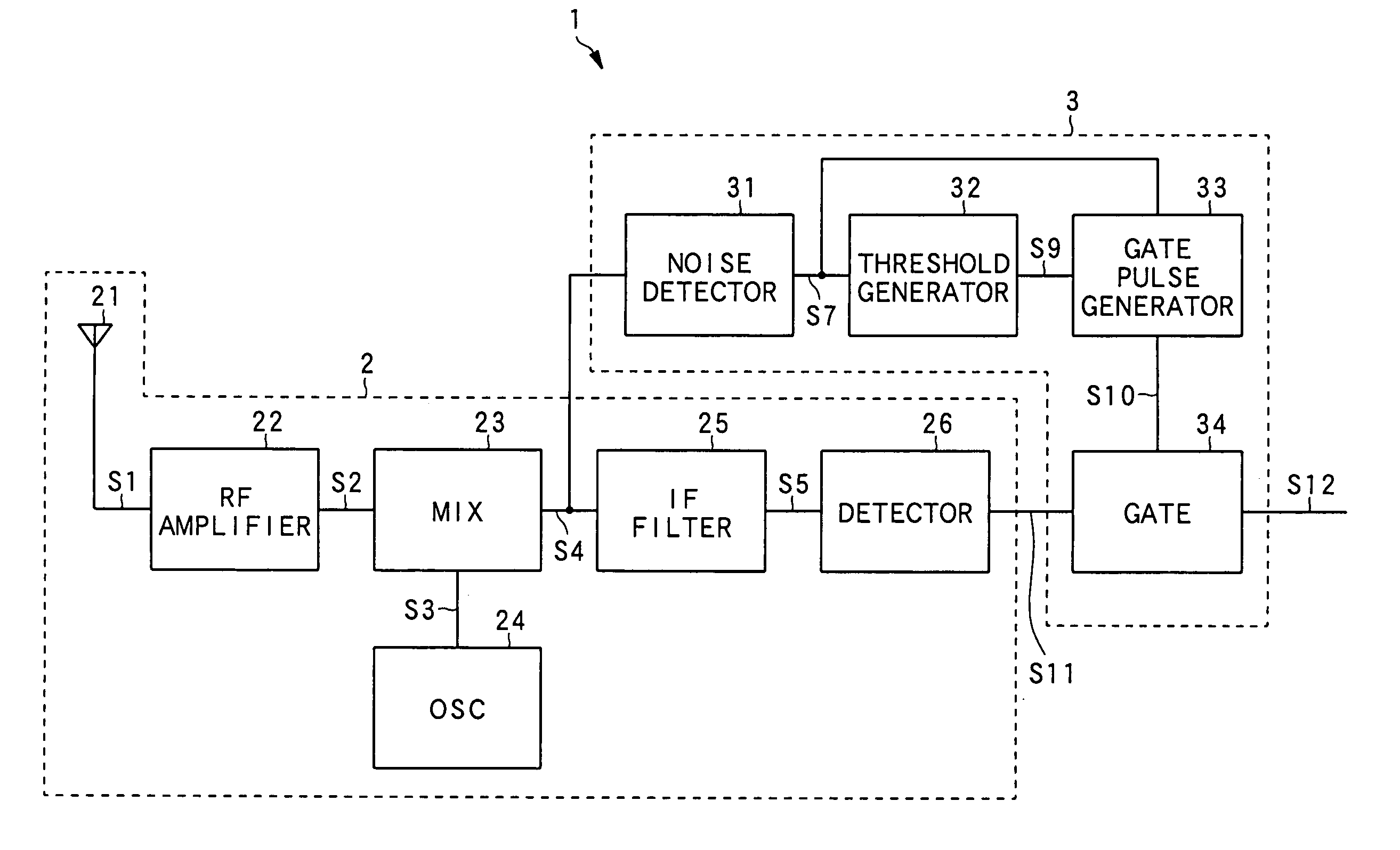
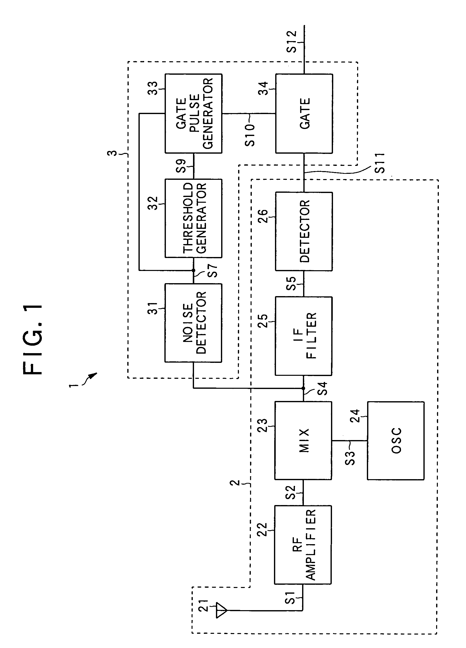
[0031]FIG. 1 is a block diagram showing the configuration of a noise eliminating apparatus and a receiver of a first embodiment. As shown in FIG. 1, a receiver 1 comprises: a receiving device 2 including an antenna 21, a high frequency amplifier (RF amplifier) 22, a frequency mixer (MIX) 23, a local oscillator (OSC) 24, an intermediate frequency filter (IF filter) 25, and a detector 26; and a noise eliminating apparatus 3 including a noise detector 31, a threshold generator 32, a gate pulse generator 33, and a gate 34.
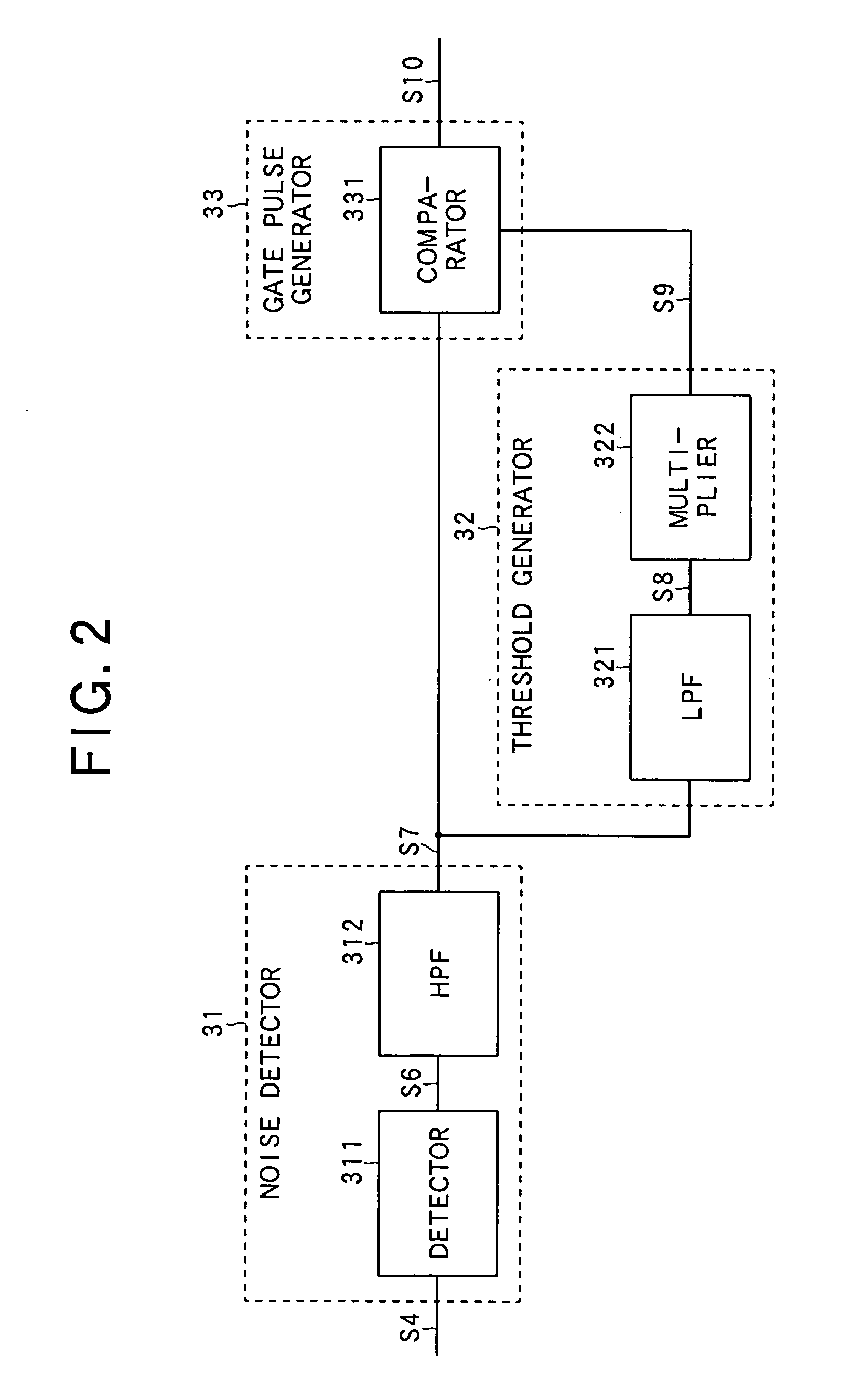
[0032] As the receiving device 2, a general super heterodyne receiver is used. An electromagnetic wave is received from the space by the receiver 1 via the antenna 21. The RF amplifier 22 amplifies a high-frequency reception signal S1 received by the receiver 1 via the antenna 21. The frequency mixer 23 mixes a high-frequency signal S2 amplified by the RF amplifier 22 with an oscillation signal S3 of the local oscillator 24, and converts the frequency difference betwe...
second embodiment
[0044]FIG. 5 is a block diagram showing the configuration of a main portion of a noise eliminating apparatus of a second embodiment. As shown in FIG. 5, the second embodiment is similar to the first embodiment except that a holding circuit 35 and a switch 36 are provided between the threshold generator 32 and the gate pulse generator 33. The holding circuit 35 retains the threshold S9 output from the threshold generator 32. The switch 36 switches between the threshold S9 output from the threshold generator 32 and a threshold S13 held in the holding circuit 35 and supplies the selected threshold to the gate pulse generator 33. The other configuration is the same as that of the first embodiment. The same reference numerals are designated to the same components as those of the first embodiment and their description will not be repeated.
[0045]FIG. 6 is a circuit diagram conceptually showing the configuration of the holding circuit 35 and the switch 36. As shown in FIG. 6, the holding c...
PUM
 Abstract
Description
Claims
Application Information
 - R&D
- Intellectual Property
- Life Sciences
- Materials
- Tech Scout
- Unparalleled Data Quality
- Higher Quality Content
- 60% Fewer Hallucinations
Browse by: Latest US Patents, China's latest patents, Technical Efficacy Thesaurus, Application Domain, Technology Topic, Popular Technical Reports.
© 2025 PatSnap. All rights reserved.Legal|Privacy policy|Modern Slavery Act Transparency Statement|Sitemap|About US| Contact US: help@patsnap.com


