Internal combustion engine controller

a technology for internal combustion engines and controllers, applied in electric control, ignition automatic control, speed sensing governors, etc., can solve the problems of difficulty in pre-setting the time for retarding the ignition timing, engine speed is likely to suddenly decrease, trouble is likely to arise, etc., and achieve the effect of preventing engine speed

Active Publication Date: 2005-07-07
TOYOTA JIDOSHA KK
View PDF2 Cites 20 Cited by
  • Summary
  • Abstract
  • Description
  • Claims
  • Application Information

AI Technical Summary

Benefits of technology

[0007] The present invention has been made for solving the above problems, and an object of the invention is to provide the internal combustion engine controller that is adapted so that without

Problems solved by technology

However, it is difficult to preset the time for retarding the ignition timing, since the rotational behavior of the engine after it has been started changes under the influence of air density, an air/fuel ratio (volatility of the fuel), friction (oil viscosity and a rod-cylinder fit), and other factors.
Trouble is likely to arise, depending on the particular relationship between the retarding time of the ignition timing and the rotational behavior after th

Method used


Image

  • Internal combustion engine controller
  • Internal combustion engine controller
  • Internal combustion engine controller

Examples


first embodiment

[0022] A first embodiment of the present invention is described below with reference to the accompanying drawings.

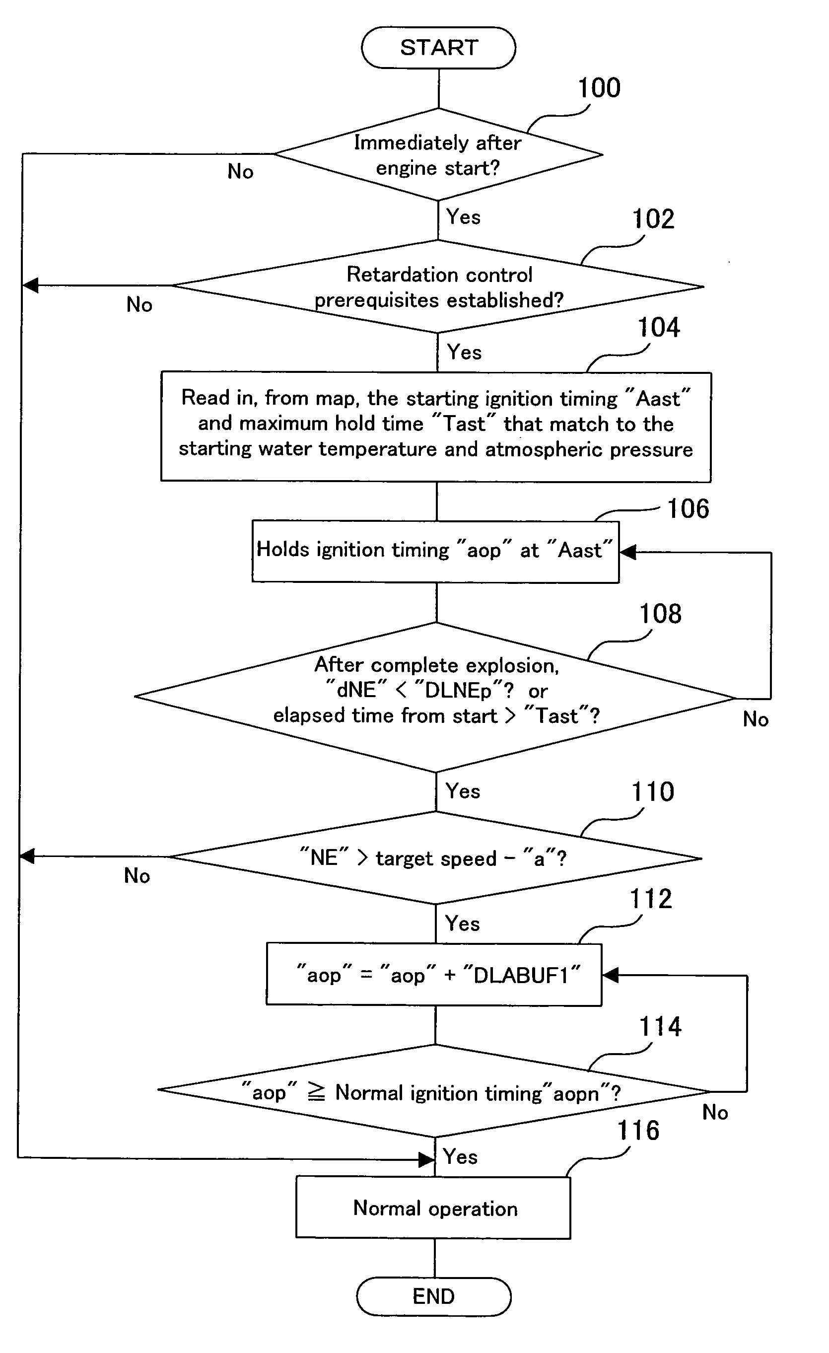
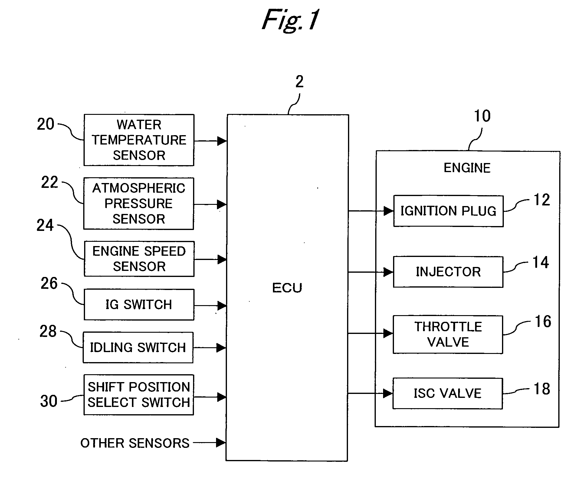
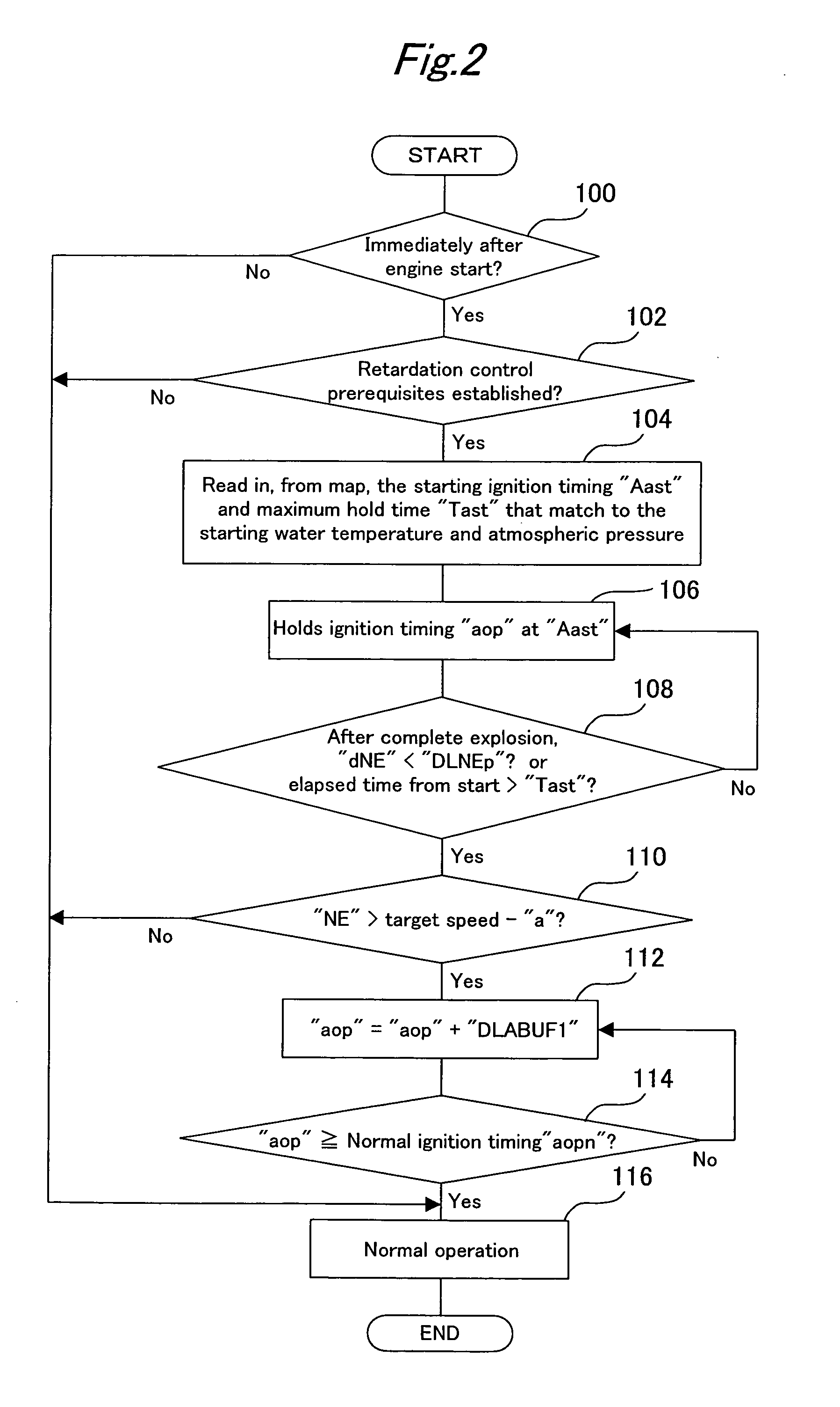
[0023] FIGS. 1 to 5D are diagrams for explaining an internal combustion engine controller according to the first embodiment of the present invention. The controller according to the present embodiment is constructed as an electronic control unit (ECU) 2. In accordance with output signals from a plurality of sensors and switches, the ECU 2 synthetically controls various equipments relating to an operating state of an internal combustion engine 10. In the present embodiment, as shown in a block diagram of FIG. 1, a water temperature sensor 20, an atmospheric pressure sensor 22, an engine speed sensor 24, an ignition switch (IG switch) 26, an idling switch 28, and a shift position select switch 30 are connected to an input end of the ECU 2. Also, ignition plugs 12, an injector 14, a throttle valve 16, and an idling speed control (ISC) valve 18 are connected to an output en...

second embodiment

[0045] A second embodiment of the present invention is described below with reference to FIGS. 6 to 8.

[0046]FIG. 6 is a block diagram showing a configuration of an internal combustion engine controller according to the second embodiment of the present invention. In FIG. 6, sections common to those of the first embodiment described above are each assigned the same reference number, and descriptive overlaps concerning these sections are omitted herein.

[0047] The present embodiment assumes a hybrid vehicle (parallel type of hybrid vehicle) that has an internal combustion engine 10 and a motor generator (hereinafter, referred to simply as motor) 40 in parallel to generate driving power. The motor 40 functions as a motor by receiving the electric power supplied from a battery not shown, and functions as a generator by receiving the driving power supplied from the engine 10. The present embodiment activates the motor 40 as a generator when the engine 10 is started, and uses an ECU 2 to ...


PUM


Abstract

From the start of the engine to the detection of an engine speed peak, a control parameter (e.g., ignition timing) different from an air intake rate relating to an engine output is set to a value at which the engine output decreases than at an idling value. After detection of the peak, the control parameter is adjusted to the idling value.

Description

BACKGROUND OF THE INVENTION [0001] 1. Field of the Invention [0002] The present invention relates to a control technique for internal combustion engines, and more particularly, to a control technique for preventing an engine speed from abruptly increasing to an excessively high speed immediately after the start of the engine. [0003] 2. Background Art [0004] Immediately after the start of an internal combustion engine, the engine speed abruptly increases well above an idling speed. This is due to the fact that whereas the internal pressure of the air intake pipe under normal operating conditions including an idling state is a negative pressure, the internal pressure of the air intake pipe during engine start is an atmospheric pressure. During start of the engine, as in an idling state, a throttle valve is closed and an ISC valve is opened to a required idling angle position. Since the air density inside the air intake pipe during the start increases above the air density reached unde...

Claims


Application Information

Patent Timeline
IPC IPC(8): F02D29/02F02D31/00F02D41/06F02D41/08F02D45/00F02P5/15
CPCF02D31/008F02D41/062F02D41/08Y02T10/46F02D2200/0611F02D2250/24F02P5/1506F02D2041/2048Y02T10/40
Inventor TAKAMA, YASUYUKIYOSHIOKA, MAMORU
Owner TOYOTA JIDOSHA KK
Why Eureka
Try Eureka