Curved micromachined ultrasonic transducer arrays and related methods of manufacture

Active Publication Date: 2005-07-07
GENERAL ELECTRIC CO
View PDF5 Cites 124 Cited by
  • Summary
  • Abstract
  • Description
  • Claims
  • Application Information

AI Technical Summary

Benefits of technology

[0016] The present invention is directed to curved sensor devices comprising an array of micromachined sensors, such as MUTs. In the case of MUTs, such structures

Problems solved by technology

However, curvature in both directions is severely limited.
If an alternating voltage drives the membrane, significant ultrasound generation results.
Conversely, if the membrane is biased app

Method used


Image

  • Curved micromachined ultrasonic transducer arrays and related methods of manufacture
  • Curved micromachined ultrasonic transducer arrays and related methods of manufacture
  • Curved micromachined ultrasonic transducer arrays and related methods of manufacture

Examples


Embodiment Construction

[0031] The innovation disclosed here is a unique method of making curved MUT arrays. For the purpose of illustration, various embodiments of the invention will be described that utilize capacitive micromachined ultrasonic transducers (cMUTs). However, it should be understood that the aspects of the invention disclosed herein are not limited to use of cMUTs, but rather may also employ pMUTs.

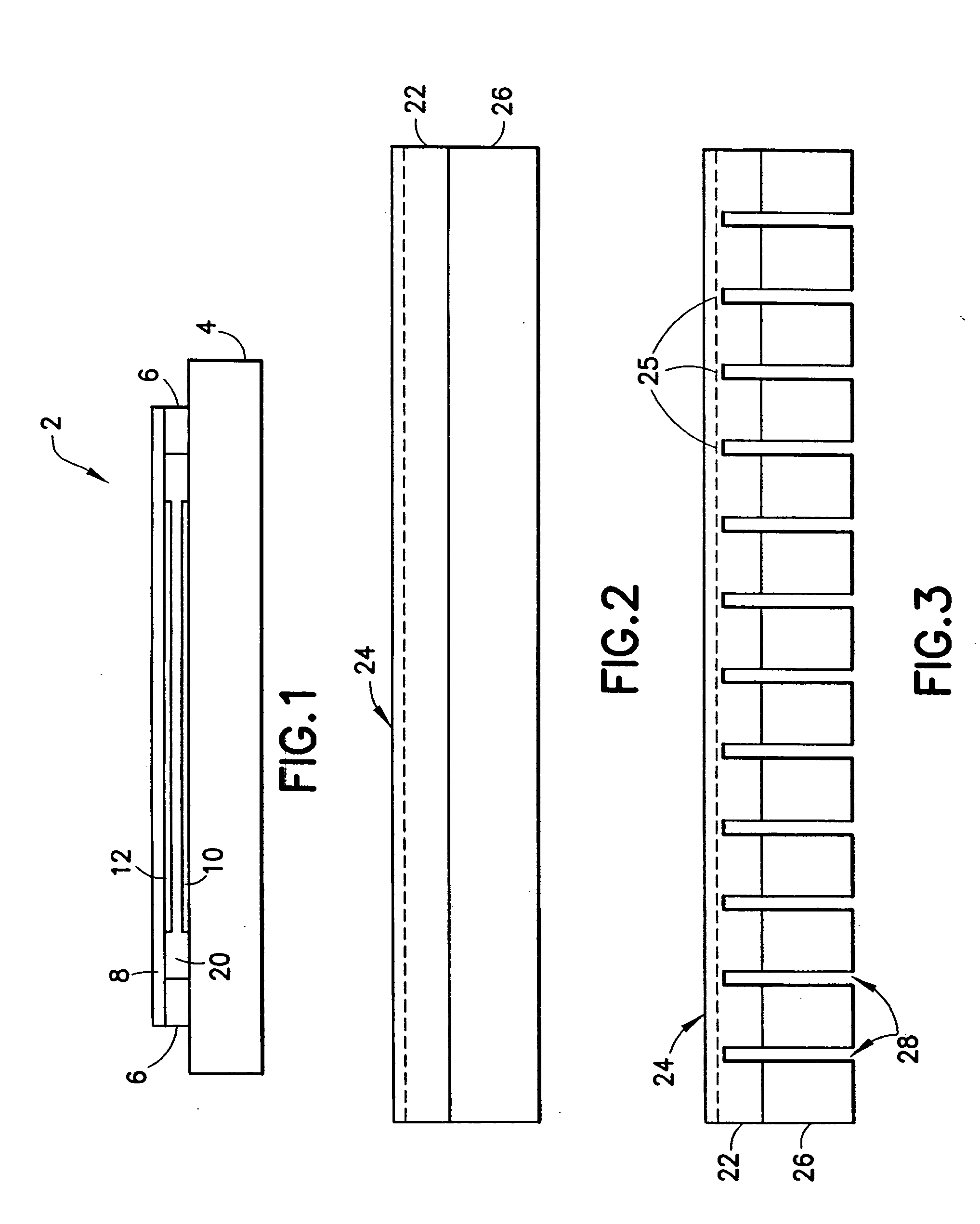
[0032] Capacitive micromachined ultrasound transducers are silicon-based devices that comprise small (e.g., 50 μm) capacitive “drumheads” or cells that can transmit and receive ultrasound energy. Referring to FIG. 1, a typical cMUT cell 2 is shown in cross section. An array of such cMUT transducer cells is typically fabricated on a substrate 4, such as a silicon wafer. For each MUT transducer cell, a thin flexible membrane or diaphragm 8, which may be made of silicon, silicon nitride, or other suitable material, is suspended above the substrate 4. The membrane 8 is supported on its periphery by a...


PUM

PropertyMeasurementUnit
Levelaaaaaaaaaa

Abstract

A curved sensor device, such as an ultrasonic transducer array, is fabricated from a flat micromachined sensor (such as cMUT or pMUT) array constructed using micromachined electromechanical systems (MEMS) techniques. The device comprises: a support structure comprising a spine having a profile that is generally curved and a multiplicity of teeth extending from one side of the curved spine; and a multiplicity of sensors built on the support structure. The spine can be bent forward or backward and attached to a curved front face of a support member, thereby causing the sensors to adopt a curved array.

Description

BACKGROUND OF THE INVENTION [0001] This invention generally relates to arrays of micromachined sensors, including but not limited to micromachined ultrasonic transducers (MUTs). One specific application for MUTs is in medical diagnostic ultrasound imaging systems. Another specific example is for non-destructive evaluation (NDE) of materials, such as castings, forgings, or pipelines. However, the curved sensor arrays disclosed herein are not limited to ultrasound transducers, but rather may also comprise, e.g., temperature, pressure, or optical sensors. [0002] Conventional ultrasound imaging systems comprise an array of ultrasonic transducers that are used to transmit an ultrasound beam and then receive the reflected beam from the object being studied. Such scanning comprises a series of measurements in which the focused ultrasonic wave is transmitted, the system switches to receive mode after a short time interval, and the reflected ultrasonic wave is received, beamformed and proces...

Claims


Application Information

Patent Timeline
IPC IPC(8): G01N29/24A61B8/00B06B1/02B81B1/00B81B3/00B81B7/04B81C1/00G01S7/521H01L27/20H01L41/08H04R17/00
CPCG01N29/2406B06B1/0292
Inventor FISHER, RAYETTE A.MILLS, DAVID M.SMITH, LOWELL SCOTTLEWANDOWSKI, ROBERT S.
Owner GENERAL ELECTRIC CO
Why Eureka
Try Eureka