Transmit-receive coil system for nuclear quadrupole resonance signal detection in substances and components thereof

a technology of quadrupole resonance signal and transmit-receive coil, which is applied in the direction of antennas, geological measurements, reradiation, etc., can solve the problems of low q factor design, waste power irradiation into a non-usable volume, and the signal voltage measured from an nqr sample is typically very small, so as to prevent coupling

Inactive Publication Date: 2005-07-07
QRSCI
View PDF16 Cites 44 Cited by
  • Summary
  • Abstract
  • Description
  • Claims
  • Application Information

AI Technical Summary

Benefits of technology

[0041] Preferably, the electric field shield is disposed around the inside of the coil to reduce the spatial dimensions of the electric field of the coil and direct the electric field away from the item being scanned. This prevents coupling between the electric field and the item being scanned, and it also stops the electric field signals being coupled back into the transmit-receive antenna.

Problems solved by technology

The signal voltage measured from an NQR sample is typically very small and is susceptible to noise interference.
This noise interference may originate from external sources such as radio transmitters, internal noise from the machine's electronics, or the sample contained within the machine.
Both of the latter coil designs suffer from low Q factors as compared to a single turn coil sheet.
The spiral and meanderline coils also suffer from the fact that they emit RF fields on both sides of the spiral or meanderline, hence they waste power irradiating into a non-usable volume.
Furthermore, large spiral coils with many turns also have high inductances, which means they will be self resonant at frequencies which are below or close to the frequency of interest, making them unsuitable for NQR detection of large volume packages.
Large solenoidal multi-turn coils also cannot be used for large volume package scanning because their inductances are too high, and typically they will be close to or will self resonate at the frequencies of interest.

Method used


Image

  • Transmit-receive coil system for nuclear quadrupole resonance signal detection in substances and components thereof
  • Transmit-receive coil system for nuclear quadrupole resonance signal detection in substances and components thereof
  • Transmit-receive coil system for nuclear quadrupole resonance signal detection in substances and components thereof

Examples


first embodiment

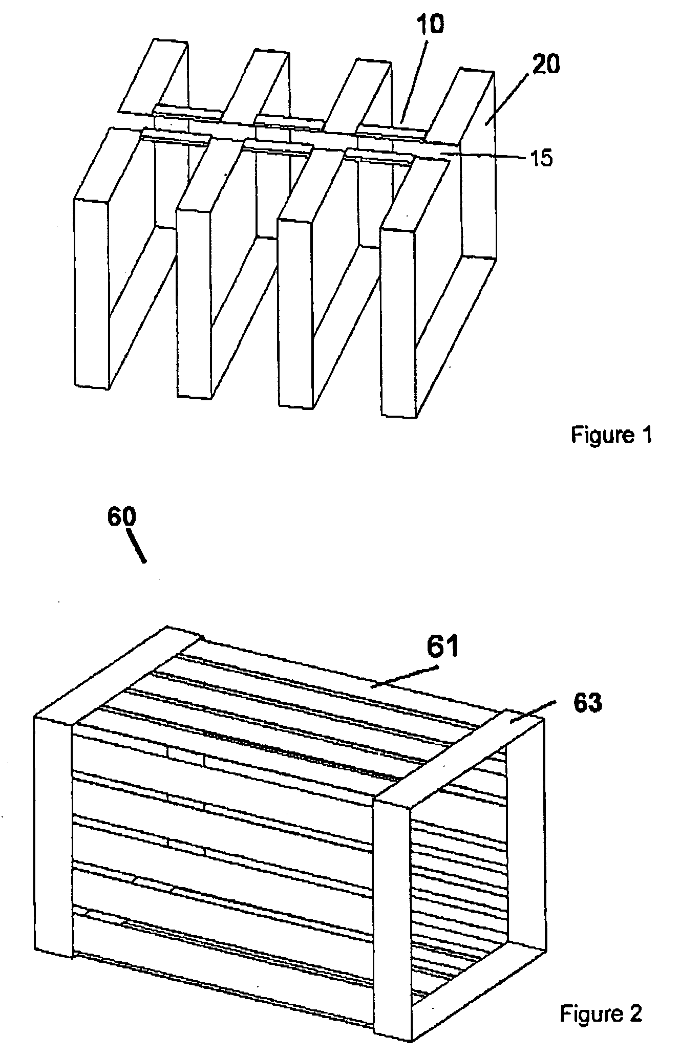
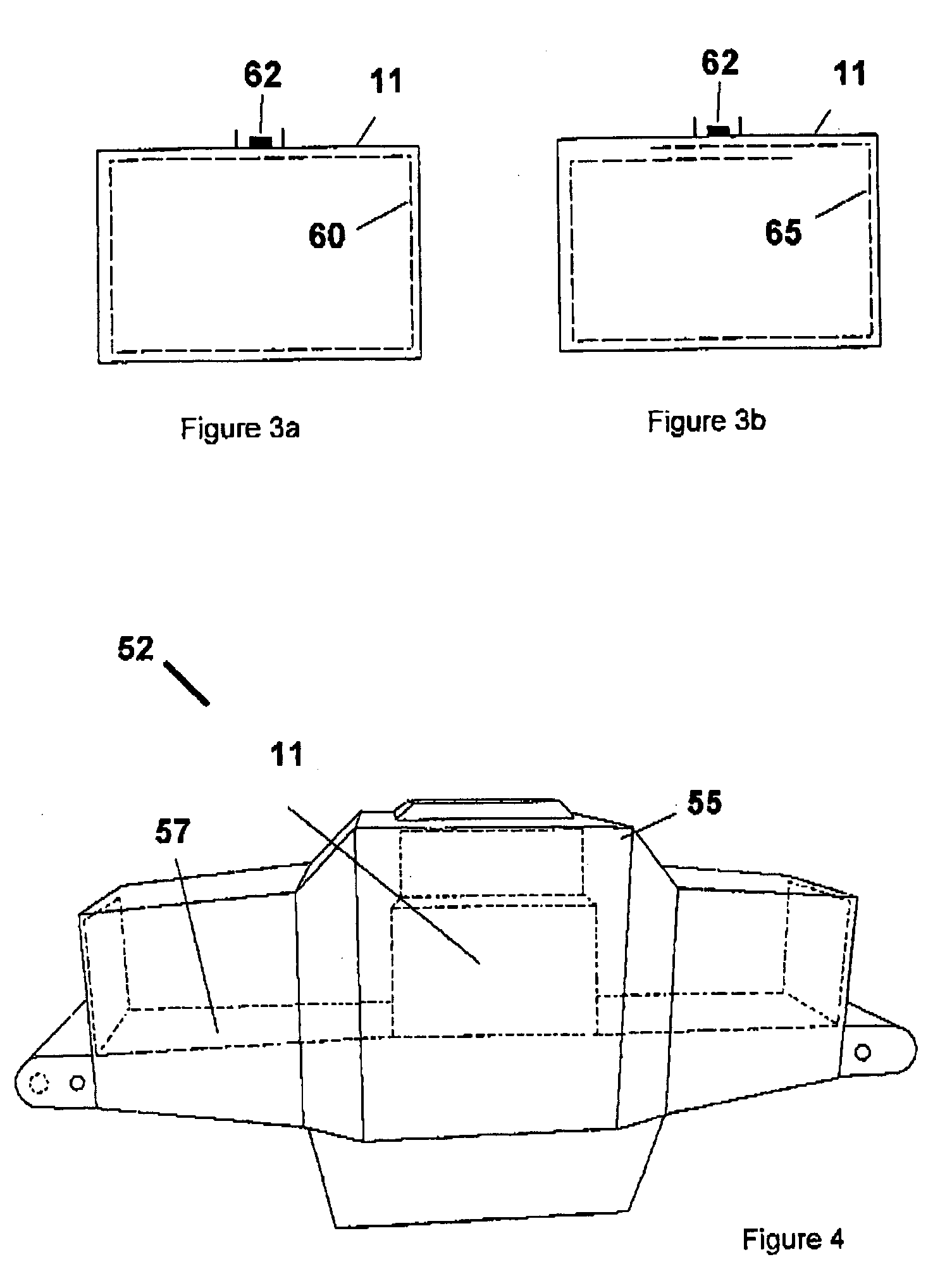
[0096] The first embodiment is directed towards an antenna and shield apparatus comprising a coil assembly 11 of the type shown in FIG. 1, an electric field shield 60 of the type shown in FIGS. 2 and 3a, and an outer shield 52 of the type shown in FIGS. 4 and 5.

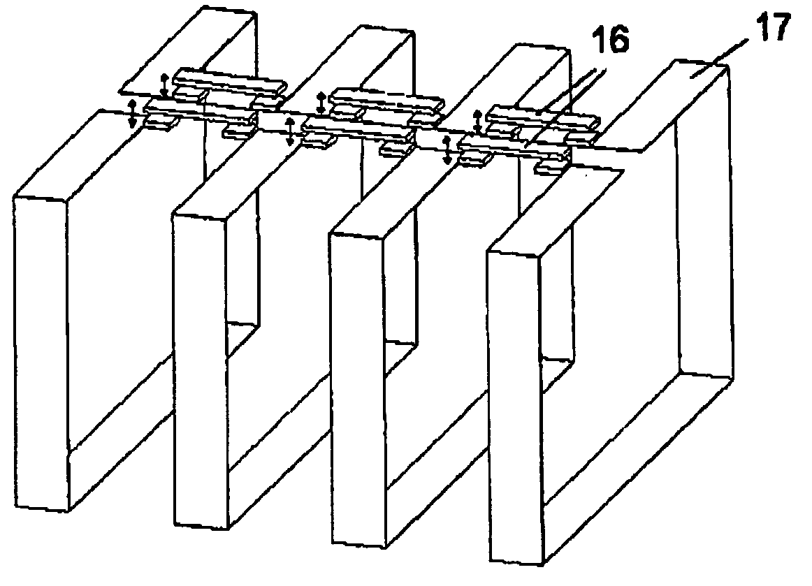
[0097] The coil assembly 11, as shown in FIG. 1, comprises a plurality of loop segments 20 made out of flat sheet electrical conducting material. The loop segments 20 are axially spaced in parallel alignment with each other about a central axis to constitute a first set of coils. Each of the loop segments 20 is interconnected along its top by a series of connectors in the form of bars 10 made from an electrically conducting material.

[0098] The loop segments 20 are configured in a rectangular shape in cross-section circumscribing a target volume within which a specimen may be disposed for scanning.

[0099] The opposing ends of each loop segment 20 at the top of the coil assembly 11 are spaced from each other to define a gap 15...

ninth embodiment

[0143] The ninth embodiment is similar to the preceding embodiment in achieving the same effect of field homogeneity by varying the separation or gap between each loop segment. As shown in FIG. 16, the loop segments 20a in the centre of the coil have large gaps between them and loop segments 20b near the ends have very narrow gaps between them.

[0144] To illustrate the improvement in field homogeneity a multiple parallel loop coil was modelled in an electromagnetic field simulator using the finite element method. The coil consisted of three basic cylindrical segments connected together. The two outer segments were 50 mm long and the centrally located inner segment was 30 mm long, with a 235 mm gap between the outer and inner segments, making a total coil length of 600 mm. FIG. 17 shows the simulated B field down the central axis of this cylindrical shape and an ordinary single turn coil. As it can be seen in FIG. 17 the field from this coil (dashed line) is almost homogeneous across ...


PUM


Abstract

An antenna and shield apparatus for detecting phenomenal signals using nuclear and electronic resonance detection technology, comprising: a transmit and receive antenna, an electric field shield 60 and an outer shield 52. The antenna is a multiple parallel loop transmit-receive antenna forming a main coil assembly 11 having a plurality of loop segments 20 optionally interconnected by connectors in the form of conducting bars 10, relays 16, or nothing. The electric field shield 60 comprises an inner sleeve of conducting material 60, 68 disposed on the inside of the coil assembly 11 for shielding the electric field emanating from the coil assembly 11 from the target volume circumscribed by the assembly. The outer shield 52 comprises a central screen portion 55, waveguides 57 at either end thereof and a sloping channel portion for interconnecting the two. The coil assembly 11 and the electric field shield 60 are housed within the outer shield 52.

Description

FIELD OF THE INVENTION [0001] This invention relates to the detection of particular substances using nuclear and electronic resonance detection technology. It has particular application, with respect to nuclear quadrupole resonance (NQR), but also application with respect to nuclear magnetic resonance (NMR), magnetic resonance imaging (MRI) and electron spin resonance (ESR) technologies. More specifically, the invention relates to a transmit-receive coil system, which has multiple coil segments that can be used for the detection of NQR signals in an NQR application (or other phenomenal signals pertaining to the particular technology used) in substances disposed within a spatially small electric field. [0002] The invention has particular, but not exclusive, utility in the detection of explosives and narcotics located within mail, airport luggage and other packages. [0003] Throughout the specification, unless the context requires otherwise, the word “comprise” or variations such as “c...

Claims


Application Information

Patent Timeline
Patent Type & Authority Applications(United States)
IPC IPC(8): G01R33/34G01R33/44H01Q7/00
CPCG01R33/34046H01Q7/00G01R33/441
Inventor FLEXMAN, JOHN HAROLDCHISHOLM, WARRICK PAULRUDAKOV, TARAS NIKOLAEVITCHMIKHALTSEVITCH, VASSILI TIMOFEEVITCHHAYES, PETER ALARIC
Owner QRSCI
Why Eureka
Try Eureka