Method and apparatus for effecting high-frequency amplification or oscillation

a technology of high-frequency amplification or oscillation, applied in the field of high-frequency circuits, can solve the problems of poor power conversion efficiency and inability to meet all aspects, and achieve the effect of improving power conversion efficiency and improving efficiency

Active Publication Date: 2005-07-07
RAYTHEON CO
View PDF6 Cites 9 Cited by
  • Summary
  • Abstract
  • Description
  • Claims
  • Application Information

AI Technical Summary

Problems solved by technology

In this regard, frequency-multiplied solid-state sources translate an input signal at one frequency into a higher harmonic frequency, but at poor power conv

Method used


Image

  • Method and apparatus for effecting high-frequency amplification or oscillation
  • Method and apparatus for effecting high-frequency amplification or oscillation
  • Method and apparatus for effecting high-frequency amplification or oscillation

Examples


Embodiment Construction

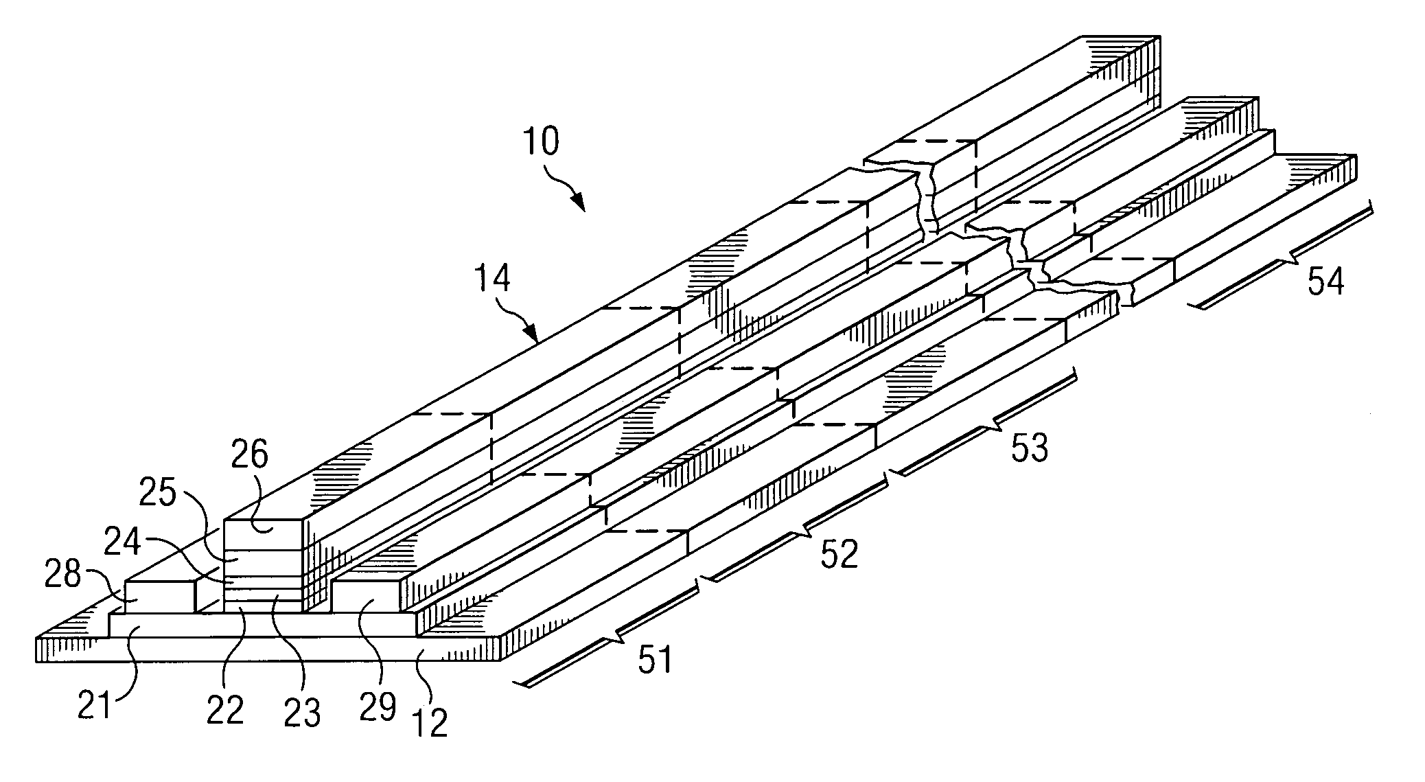
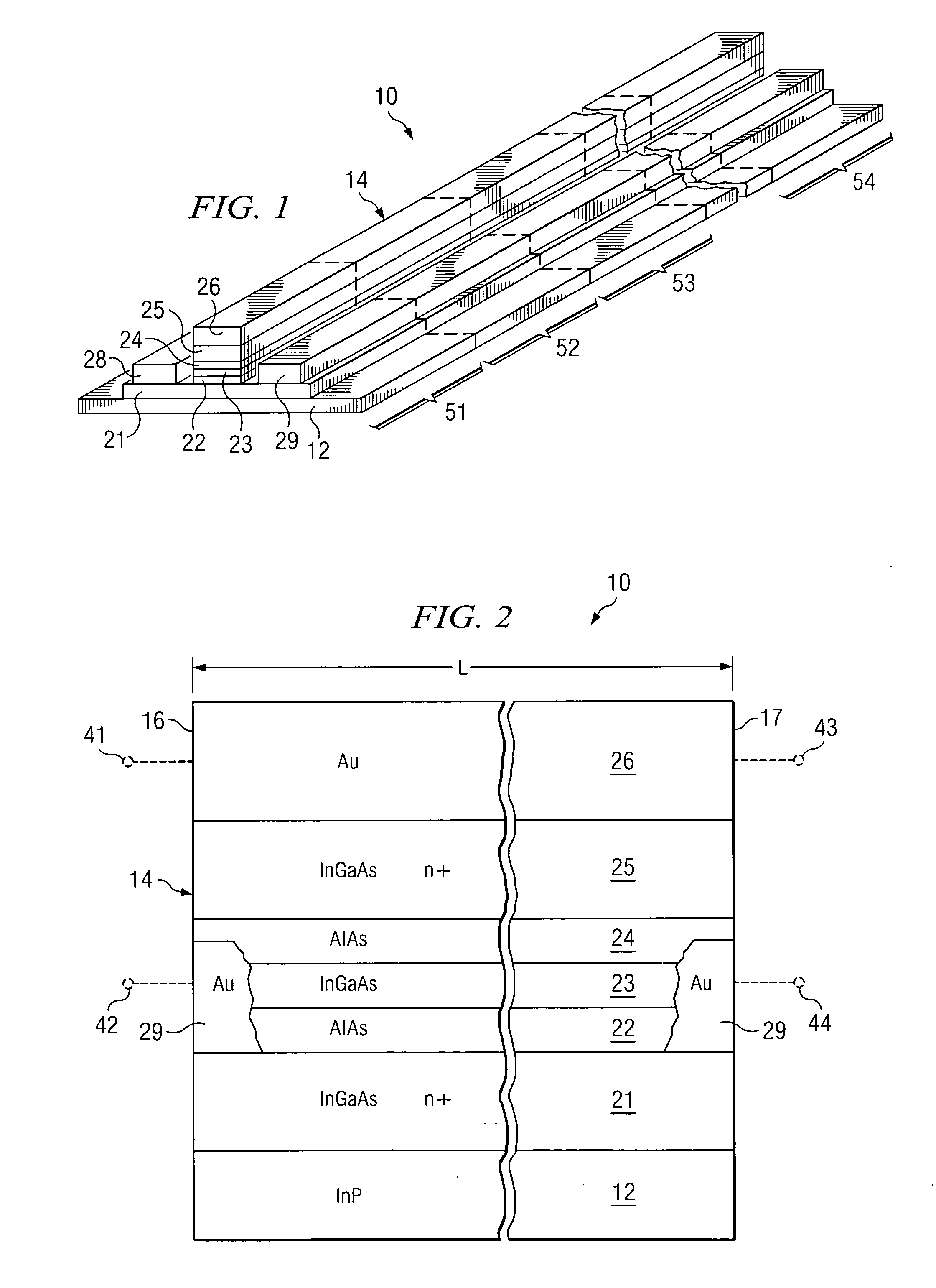
[0015]FIG. 1 is a diagrammatic perspective view of part of an apparatus which is an integrated circuit 10, and which embodies aspects of the present invention. FIG. 2 is a diagrammatic fragmentary side view of the structure shown in FIG. 1. The integrated circuit 10 includes a substrate 12 which, in the disclosed embodiment, is made of indium phosphide (InP). It should be understood that the specific materials discussed herein for various parts of the integrated circuit 10 are exemplary, and the integrated circuit 10 could be implemented using other materials and / or other semiconductor technologies.

[0016] An elongate structure 14 is formed on top of the substrate 12 and, as shown in FIG. 2, has ends 16 and 17 which are at spaced locations. The distance between the ends 16 and 17 is the electrical length L of the structure 14. The structure 14 is referred to herein as a distributed resonant tunneling diode (DRTD) structure.

[0017] The DRTD structure 14 includes an electrically condu...


PUM


Abstract

An apparatus includes a distributed resonant tunneling section with a plurality of inductive portions that are coupled in series with each other between first and second nodes, such that a respective further node is present between each adjacent pair of the inductive portions. The distributed resonant tunneling section also has a plurality of resonant tunneling device portions which are each coupled between a third node and a respective one of the further nodes.

Description

TECHNICAL FIELD OF THE INVENTION [0001] This invention relates in general to high-frequency circuits and, more particularly, to techniques for effecting high-frequency amplification or oscillation. BACKGROUND OF THE INVENTION [0002] A variety of amplifiers and oscillators exist for applications with operational frequencies below approximately 100 GHz. These include solid-state amplifiers and oscillators which are based on Gunn-effect diodes, impact avalanche transit time diodes, field effect transistors, and / or bipolar transistors. Other known approaches include vacuum sources such as klystrons, traveling wave tubes, and gyrotrons. [0003] However, there are other types of systems in which there is a need for amplifiers and / or oscillators capable of operating at higher frequencies. For example, microwave systems need high-frequency amplifiers to improve the reception of signals, need high-frequency oscillators to serve as local oscillators in receiver circuits, and need high-frequenc...

Claims


Application Information

Patent Timeline
IPC IPC(8): H01L29/88H03B7/08H03B7/14H03F3/12H03F3/60
CPCB82Y10/00H01L29/882H03F3/607H03B7/146H03B7/08
Inventor FRAZIER, GARY A.
Owner RAYTHEON CO
Why Eureka
Try Eureka