
Texture synthesis for repairing damaged images

a technology of texture synthesis and image, applied in the field of image inpainting and texture synthesis software, can solve the problems of image texture information not being retrieved, blurry without texture information, and complicated texture features of images

Active Publication Date: 2005-07-07
ARCSOFT
View PDF3 Cites 25 Cited by
  • Summary
  • Abstract
  • Description
  • Claims
  • Application Information

AI Technical Summary

Benefits of technology

"The invention is a method for creating texture in an image. It involves selecting a target patch of the image and a sample patch from which to fill the target patch. The method then calculates differences between the target patch and the sample patch in two areas. These differences are then weighted and summed to create a distance between the target patch and the sample patch. The technical effect of this method is that it allows for the creation of detailed and realistic texture in images."

Problems solved by technology

Many damaged images look fine after being repaired by the aforementioned inpainting methods.
However, these methods have a common shortcoming: all of them cannot retrieve the texture information of the image.
This shortcoming is not very obvious when only a small area of the image is damaged.
When a large area of the image is damaged, the result looks blurry without texture information and can be easily detected by the human eyes.
However, the actual images in practice (such as natural images) often do not have features with repetitive texture.
Furthermore, the texture features of these images are complicated by their environment such as lighting.
Repairing images using the aforementioned texture synthesis methods without addressing these problems will not produce a satisfactory result.

Method used


Image

  • Texture synthesis for repairing damaged images
  • Texture synthesis for repairing damaged images
  • Texture synthesis for repairing damaged images

Examples


Embodiment Construction

Problems of a Conventional Patched-Based Sampling Algorithm

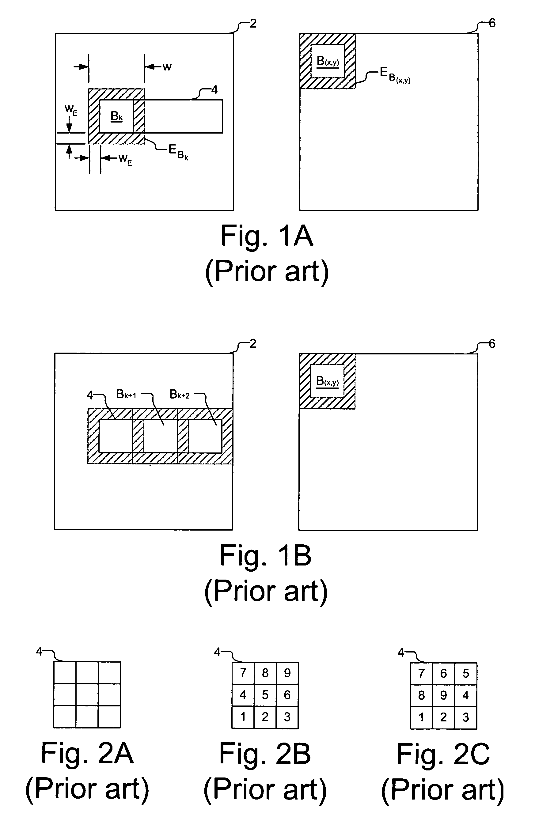
[0014] Liang et al. discloses a patch-based sampling algorithm for synthesizing textures from a sample. This sampling algorithm is hereafter explained in reference to FIG. 1A where an image 2 has a target area 4 to be filled with textures from a sample texture 6. Target area 4 is divided into target patches Bk having a patch size of w by w (only one is labeled for clarity), where k is a variable. If the width or the height of target area 4 is not a multiple of w, the size of the last row and the last column of target patches is defined as:

w*w1, w2*w,   (1)

w1=W mod w, w2=H mod w,   (2)

where W and H express the width and height, respectively, and mod is the function that calculates the residual of W or H divided by w.

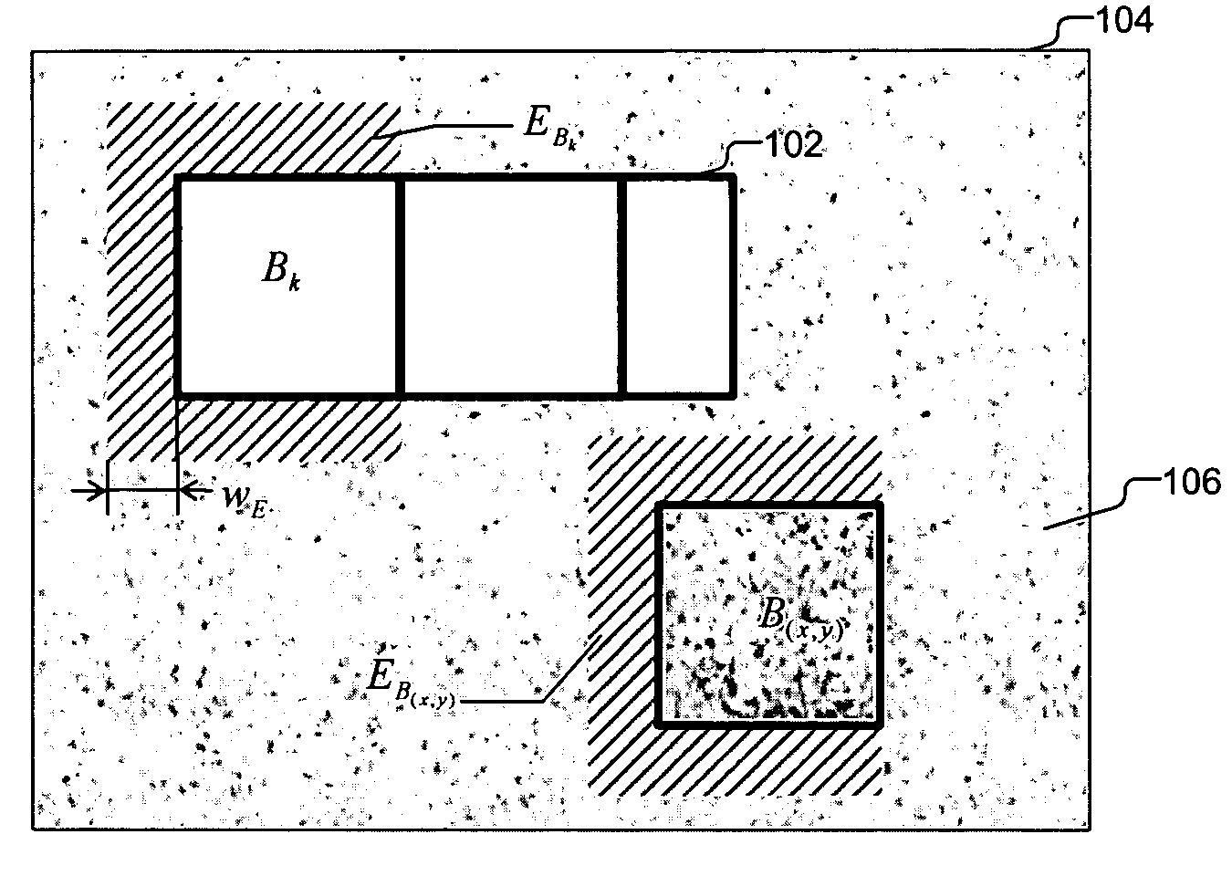
[0015] Each target patch Bk includes a boundary zone EBk having a width wE surrounding the target patch. Boundary zone EBk includes known texture from image 2 and derived texture from filling in other surro...


PUM


Abstract

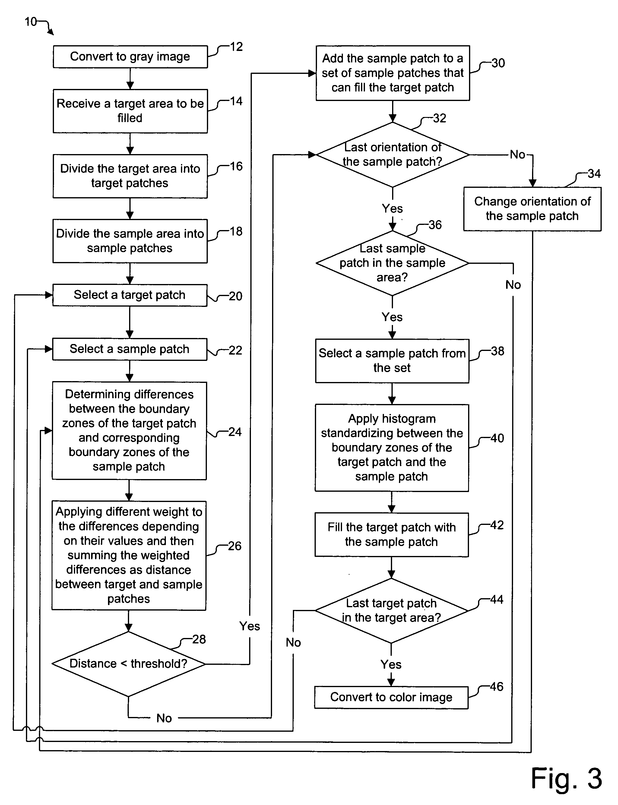
A method for generating texture includes (1) selecting a target patch to be filled in a image, (2) selecting a sample patch as a candidate for filling the target patch, (3) determining a first difference between a first area surrounding the target patch and a corresponding first area surrounding the sample patch, and a second difference between a second area surrounding the target patch and a corresponding second area surrounding the sample patch, (4) multiplying a larger of the first difference and the second difference with a first weight factor, and a smaller of the first difference and the second difference with a second weight factor, and (5) summing the weighted first difference and the weighted second difference as a distance between the target patch and the sample patch.

Description

FIELD OF INVENTION [0001] This invention relates to software for image inpainting and texture synthesis. DESCRIPTION OF RELATED ART [0002] Damaged images can be repaired by professional artists using a technique called inpainting. Various software inpainting techniques have been developed to undetectably repair images like professional artists. Bertalmio et al. proposes a method based on information propagation. M. Bertalmio, G. Sapior, V. Caselles, and C. Ballester, “Image Inpainiting,” Computer Graphics, Proceedings of SIGGRAPH, pp. 417-424, New Orleans, July 2000. It takes the known gray values of the points in the boundary of the damaged areas and propagates these gray values to the damaged area along the direction which has a small gradient. Chan et al. proposes a method that repairs image by solving the Partial Differential Equation (PDE). T. Chan, A. Marquina, and P. Mulet, “High-Order Total Variation-Based Image Restoration,” SIAM Journal on Scientific Computing, pp. 503-516...

Claims


Application Information

Patent Timeline
Patent Type & Authority Applications(United States)
IPC IPC(8): G06T5/00G06T11/00G09G5/00
CPCG06T11/001G06T5/005G06T5/77
Inventor ZHU, YUNFANGWANG, HUIQIONGJIN, YIQINGWU, DONGHUIZHOU, LINGXIANG
Owner ARCSOFT
Learn More