Integrated laser cavity with transverse flow cooling

a laser cavity and transverse flow technology, applied in lasers, laser cooling arrangements, laser details, etc., can solve the problems of difficult manufacturing, inefficient heat removal, and laser system, and achieve the effects of increasing the cross sectional area of the internal coolant passage, increasing the stability of the laser resonator, and increasing the flow rate of coolan

Inactive Publication Date: 2005-07-07
AIKEN STEPHEN R
View PDF3 Cites 9 Cited by
  • Summary
  • Abstract
  • Description
  • Claims
  • Application Information

AI Technical Summary

Benefits of technology

[0009] It is feature of the embodiment for a housing to integrate the optical coupling chamber, coupling chamber end reflectors, laser excitation source and lasing medium into a simplified structure.
[0012] It is yet another feature to yield a uniform coolant temperature across the lamp and laser rod because the flow direction is transverse as compared to a longitudinal coolant flow method. With longitudinal coolant flow, the coolant temperature rises linearly as it flows down the longitudinal axis of the lasing medium and excitation source. By eliminating this gradient with transverse flow, increased laser resonator alignment stability can be provided.
[0013] It is yet another feature to increase coolant flow rates through an increase of the internal coolant passage cross sectional area, while maintaining an overall compact laser structure. Cooling capacity can thus be increased for removal of heat from the laser excitation source.
[0014] In accordance with another feature, two cavity half shells include the optical coupling element, which has a optimal cross-section for laser excitation (e.g. cylindrical, elliptical, etc.) and can include the contoured ends appropriate to the specific laser medium used (e.g., solid state crystal rod, etc.). This design is adaptable to allow the optical coupling element to include a variety of cross sections with reflective or diffuse surface preparations (or a combination thereof) to optimally couple the laser excitation energy to the lasing media.

Problems solved by technology

Unfortunately, in addition to the noted multi-element assemblies and thermal / mechanical issues associated with the prior art, such laser systems are further found to be inefficient in heat removal, difficult to manufacture and subject to coolant leakage because of their designs.
Flash lamps will either fail or be inefficient because of inadequate cooling, or a lasing system will experience misalignment over the laser resonator due to non-uniform cooling and / or liquid flow induced vibrations.
A plurality of sealing gaskets or O-rings meant to seal a housing and reduce vibration physically increases the opportunity for coolant leakage and system complexity.

Method used


Image

  • Integrated laser cavity with transverse flow cooling
  • Integrated laser cavity with transverse flow cooling
  • Integrated laser cavity with transverse flow cooling

Examples


Embodiment Construction

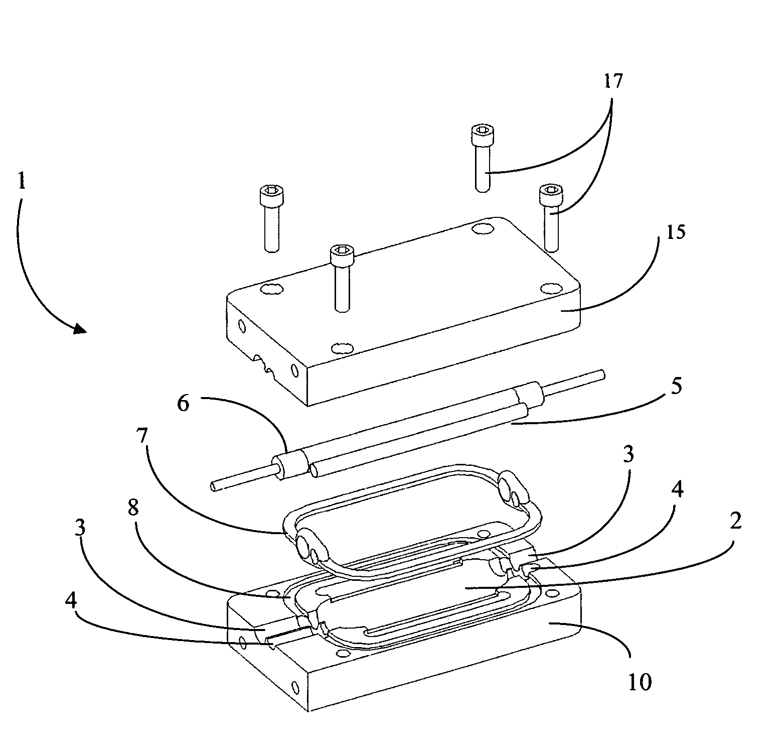
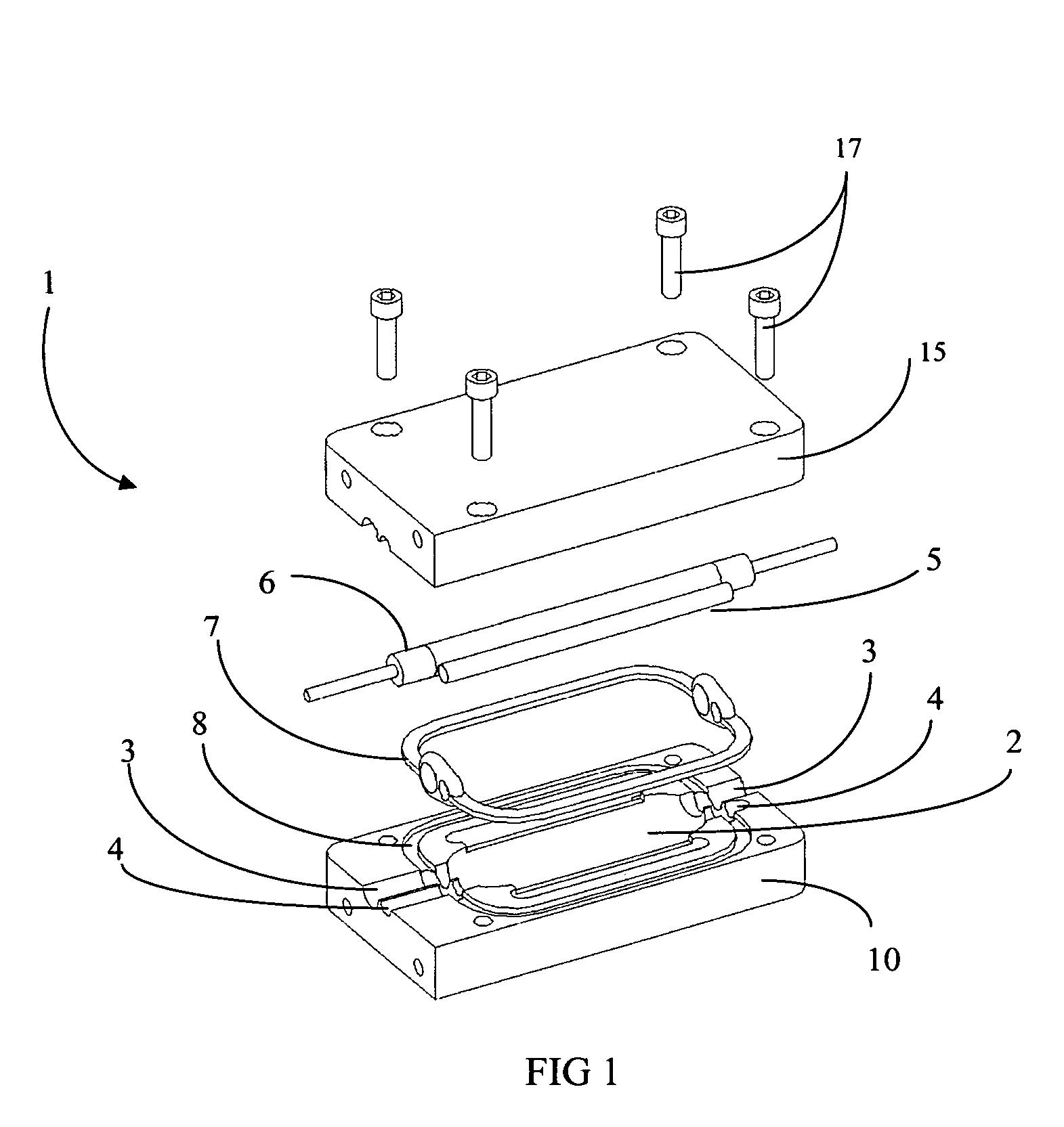
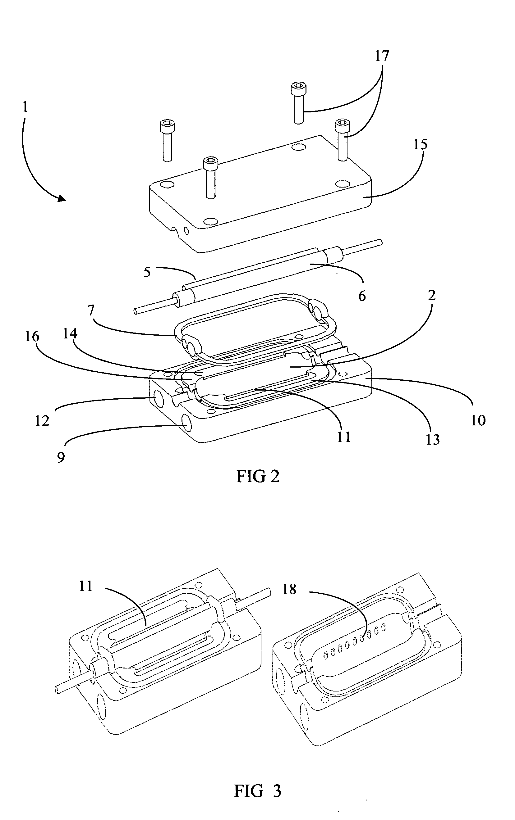
[0020] The particular values and configurations discussed in these non-limiting examples can be varied and are cited merely to illustrate an embodiment of the present invention and are not intended to limit the scope of the invention.

[0021] While the primary embodiment of the descriptions contained herein are illustrated by solid state crystal laser media (e.g. Er:YAG, etc.) excited or “pumped” by an electrical discharge through a flash lamp, it is to be understood that the disclosed concepts apply to, and include alternate laser media (e.g. dyes in cuvettes, quantum dot materials, etc.) and excitation sources (e.g. semiconductor diode lasers, etc.). To that extent terms such as “excitation source,”“pump,”“pump source” and “flash lamp” can be used interchangeably to designate sources of optical excitation for the laser media. Similarly, terms such as “laser media,”“lasing medium,”“laser rod,”“rod,” and “laser resonator” can also be used interchangeably are known as equivalent by th...


PUM


Abstract

A laser cavity includes two half shells adapted to be held together forming a sealed, integrated laser structure. The laser cavity is adapted for retaining an excitation source and a lasing medium. At least one coolant passage formed in at least one of the half shells causes liquid to flow transversely over the excitation source and lasing medium. At least one coolant passage formed in at least one of the half shells removes liquid from the laser cavity after the liquid is caused to flow transversely over the excitation source and lasing medium. An inlet formed in at least one of the two half shells can transport liquid into the laser cavity and through the coolant passages. An outlet formed in at least one of the two half shells can remove coolant from the laser cavity after the liquid is caused to flow transversely over the excitation source and lasing medium.

Description

PRIORITY [0001] This application is a Continuation of Provisional Application No. 60 / 534,643, entitled “Integrated laser cavity with transverse flow cooling,” which was filed on Jan. 6, 2004, and to which priority is claimed.BACKGROUND [0002] The present invention is related to a handheld laser head for medical and industrial laser applications. More particularly, the present invention is related to a handheld laser head for medical and industrial laser applications including a liquid cooling chamber for maintaining continuous laser operation. [0003] Medical lasers, such as those used for skin resurfacing, wrinkle removal, tattoo removal and surgery generally include laser excitation sources such as flash lamps that generate much heat within the laser housing and therefore require cooling to prevent flash lamp failure. Liquid is well known to be used as a coolant within laser cavities wherein a flash lamp is operating. For example, U.S. Pat. No. 5,970,983 issued to Kami, teaches a s...

Claims


Application Information

Patent Timeline
Patent Type & Authority Applications(United States)
IPC IPC(8): H01S3/04H01S3/042H01S3/092
CPCH01S3/0407H01S3/092H01S3/042
Inventor AIKEN, STEPHEN R.
Owner AIKEN STEPHEN R
Why Eureka
Try Eureka