Ultra-short wavelength x-ray system

a technology of ultra-short wavelength x-ray and x-ray system, which is applied in the direction of laser details, excitation process/apparatus, electrical apparatus, etc., can solve the problem of large fluxes that are not currently produced by any source, and achieve the effect of increasing the flux, and increasing the flux of short-wavelength radiation

Active Publication Date: 2005-07-07
MICHIGAN UNIVERISTY OF
View PDF12 Cites 34 Cited by
  • Summary
  • Abstract
  • Description
  • Claims
  • Application Information

AI Technical Summary

Benefits of technology

[0007] The invention provides a method and apparatus to generate a beam of coherent light that satisfies all of requirements for uses in lithography and protein analysis, among other applications. It is based on the Thomson scattering of a high-intensity laser pulse with an electron beam that is accelerated by a synchronized laser pulse. In one aspect, a laser-accelerated electron gun is coupled with an electromagnetic wiggler or undulator. A further refinement is the operation of the device in the collective regime by means of the free-electron laser (FEL) mechanism, which increases the coherence of the light as well as increases its power. In order to operate in this collective regime, the invention provides several means by which the output of the laser-driven electron accelerator can be made relatively monoenergetic. Also disclosed are the results of simulations and calculations that confirm the attendant large increase in the x-ray power at the wavelength of interest for EUV lithography, based on the experimentally measured electron beam parameters from a laser-based accelerator. Also disclosed are methods to increase the electron flux and thus the scattered x-ray power. The inclusion of other concepts for decreasing the energy-spread of laser-based accelerators, such as laser injection of electrons (see Umstadter U.S. Pat. No. 5,789,876), increases this power even further. The invention also provides a method for seeding the amplification by the injection of radiation of the desired wavelength from a separate synchronized laser-pumped x-ray source.
[0010] Still other features include: a method to increase the flux of short-wavelength radiation by increasing the flux of laser accelerated electrons; and a method to increase the flux of short-wavelength radiation by varying the pulse duration of a scattering laser beam.

Problems solved by technology

Such large fluxes are not currently produced by any source small enough to fit on an industrial research laboratory floor.

Method used


Image

  • Ultra-short wavelength x-ray system
  • Ultra-short wavelength x-ray system
  • Ultra-short wavelength x-ray system

Examples


Embodiment Construction

[0036] The following description of the preferred embodiment(s) is merely exemplary in nature and is in no way intended to limit the invention, its application, or uses.

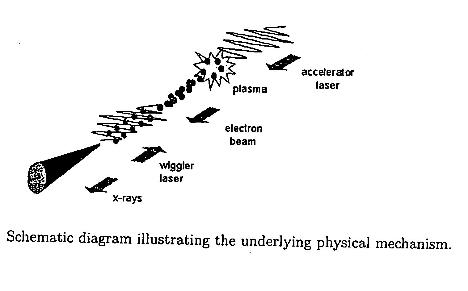
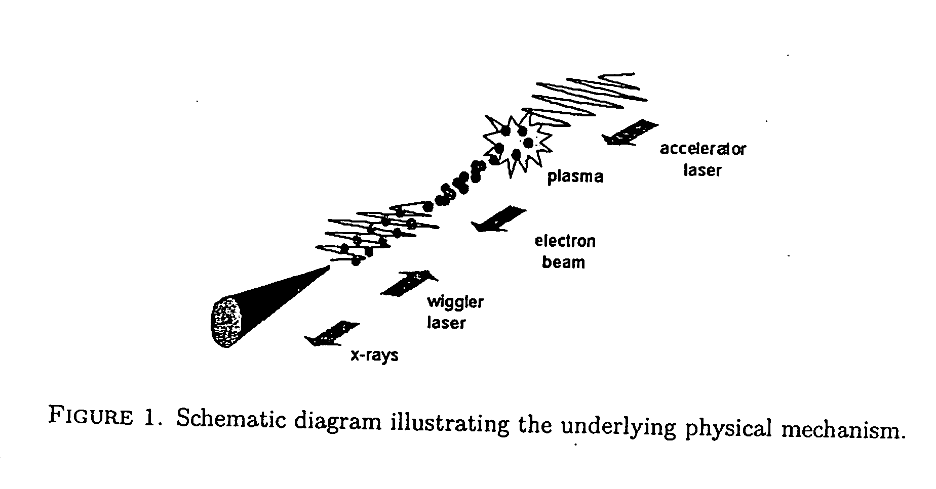
[0037] Laser-based accelerators currently produce electron beams that are well collimated (less than 1-degree divergence angle) with nanoCoulombs of charge, with sub-picosecond pulse durations and at repetition rates of 10 Hz. They are based on the generation of high amplitude plasma waves by high-power lasers, by one of several mechanisms, such as the self-modulated laser wakefield acceleration mechanism, the resonantly driven wakefield mechanism (see Umstadter U.S. Pat. No. 5,637,966), and the beatwave accelerator mechanism. One important attribute of these optically-driven accelerators as compared to their more conventional radio-frequency based counterparts is that the accelerating gradient (1 GeV / cm) is four orders of magnitude greater. Thus electron energies of 100-million electron volts (MeV) can be achieved ...


PUM


Abstract

A method and apparatus to generate a beam of coherent light including x-rays or XUV by colliding a high-intensity laser pulse with an electron beam that is accelerated by a synchronized laser pulse. Applications include x-ray and EUV lithography, protein structural analysis, plasma diagnostics, x-ray diffraction, crack analysis, non-destructive testing, surface science and ultrafast science.

Description

GOVERNMENT'S RIGHT CLAUSE [0001] This invention was made with government support provided by the Department of Energy (Grant No. DE-FG02-96ER14685) and Office of Naval Research (Grant No. N00014-01-1-0849). The government has certain rights in the invention.FIELD OF THE INVENTION [0002] The present invention relates to ultrashort-pulse-duration and high-power light sources. BACKGROUND OF THE INVENTION [0003] In order to satisfy the needs of basic research as well as industry, there is currently great interest in coherent, ultrashort-pulse-duration and high-power light sources. In basic research, large (kilometer) x-ray synchrotrons have met some of these needs, but they are extremely expensive, costing hundreds of millions of dollars. Thus, there is a need for an affordable and compact source, having a small enough footprint to fit in a university or industrial research laboratory or factory setting. Additionally, light with shorter pulse durations than are currently produced by syn...

Claims


Application Information

Patent Timeline
Patent Type & Authority Applications(United States)
IPC IPC(8): H01S3/00H01S3/09H01S3/094H01S3/0959H01S3/30
CPCA61N2005/1088H01S3/0903H01S3/30H01S3/0959H01S3/094
Inventor UMSTADTER, DONALDHE, FEILAU, Y.Y.
Owner MICHIGAN UNIVERISTY OF
Why Eureka
Try Eureka