Bearing device and motor using the bearing device

a bearing device and bearing technology, applied in sliding contact bearings, manufacturing tools, instruments, etc., can solve the problems of difficult non-contact support, difficult to produce the effect of preventing oil dispersion, and plenty of oil running out of the oil reservoir, etc., to achieve restraint of housing deformation

Inactive Publication Date: 2005-07-07
CITIZEN WATCH CO LTD
View PDF12 Cites 10 Cited by
  • Summary
  • Abstract
  • Description
  • Claims
  • Application Information

AI Technical Summary

Benefits of technology

[0016] The object of the present invention is to provide a bearing device, in which an escape of a liquid fluid (oil) is reduced, a rotating shaft is securely prevented from slipping off, and deformation of a housing is restrained when a sleeve is fixed to the housing by caulking processing, and a motor using the bearing device.

Problems solved by technology

If the oil scatters or flows out in this manner, non-contact support becomes difficult.
According to this prior art technique in which a seal portion is formed by defining a space for the oil reservoir between the sleeve and the rotating shaft, however, plenty of the oil may possibly collect in the oil reservoir and plenty of the oil may run out of the oil reservoir.
Thus, it is hard to satisfactorily produce the effect of preventing dispersion of the oil.
Thus, friction on the pivot portion increases to generate dynamic friction, and besides, the rotation of the rotating shaft is liable to be unbalanced.
If the flange engages the sleeve, moreover, the rotation of the rotating shaft is suddenly braked, so that the flange and the bearing member are heated by friction, and besides, the flange and the bearing member may possibly be broken.
According to the prior art example described above, it is hard to accurately form the space for the flange.
Since the flange continually generates the dynamic pressures in both the upward and downward directions, moreover, a great power loss is caused inevitably.

Method used


Image

  • Bearing device and motor using the bearing device
  • Bearing device and motor using the bearing device
  • Bearing device and motor using the bearing device

Examples


Embodiment Construction

[0050] (General Construction of Bearing Device)

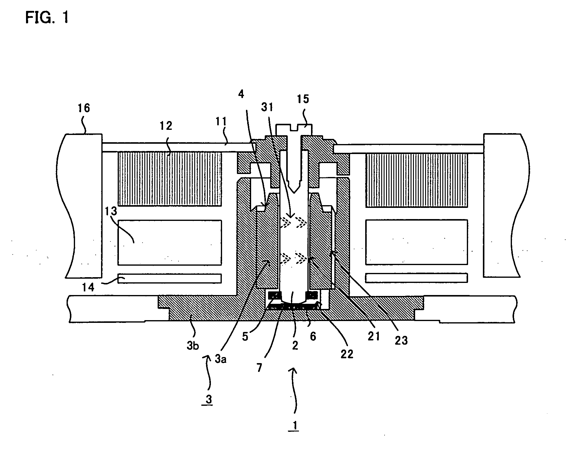
[0051] An example of a bearing device according to the present invention that is applied to a fan motor will first be described with reference to FIG. 1.

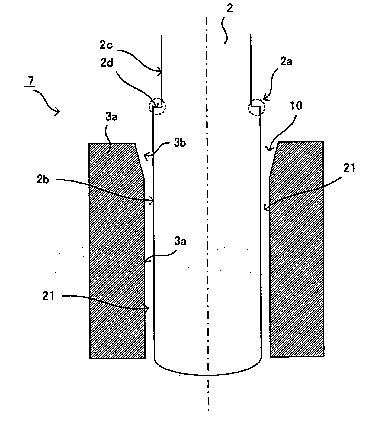
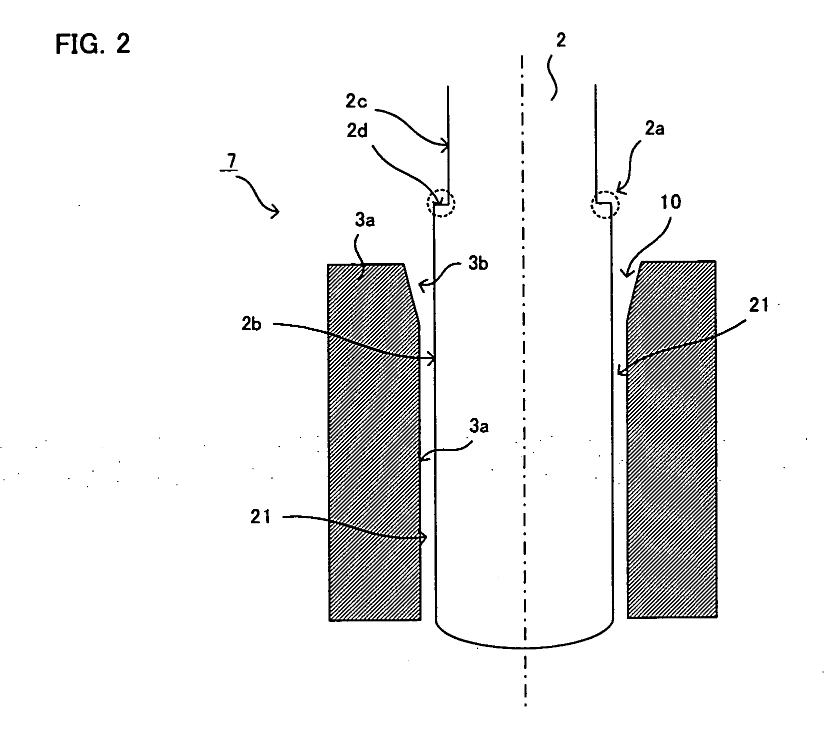
[0052] A bearing device 1 comprises a rotating shaft 2 and a bearing member 3 that supports the rotating shaft 2 for rotation. The bearing member 3 includes a sleeve 3a, which supports the rotating shaft 2 in a non-contact manner, and a housing 3b that fixes the sleeve 3a. A rotor 11 that is fitted with a fan 16 is fixed to the rotating shaft 2 by means of a fixing screw 15, whereby the fan motor is formed.

[0053] A magnet 12 on the rotor 11, a coil and a magnetic core 13, which are attached to a fixed portion of the housing 3b, and a base plate 14 that controls drive current to the coil constitute a fan motor drive mechanism.

[0054] The sleeve 3a is penetrated by a storage hole that houses the rotating shaft 2. When the rotating shaft 2 is housed in the storage hole, a radial axis ga...


PUM

PropertyMeasurementUnit
distanceaaaaaaaaaa
diameteraaaaaaaaaa
thicknessaaaaaaaaaa

Abstract

A bearing device is composed of a sleeve (3a) for supporting a rotating shaft across a radial axis gap and a housing (3b) formed with a storage hole for storing the sleeve (3a). The sleeve (3a) housed in the storage hole of the housing (3b) is fixed to the housing by applying caulking processing to a part of the inner wall of the housing in a position at a certain downward distance from the upper end of the storage hole.

Description

TECHNICAL FIELD [0001] The present invention relates to a bearing device applicable to various rotating apparatuses that require non-contact support, such as a microprocessor cooling fan motor, hard disc and optical disc rotating apparatuses, etc., and to a motor using the bearing device. BACKGROUND ART [0002] A fluid bearing device that uses dynamic pressure is known to have advantages, such as longer lifetime, quietness, and higher resistance to vibration, which are attributable to non-contact support, as well as higher rotational accuracy. An example of the conventional fluid bearing device that uses dynamic pressure will now be described with reference to FIG. 12A. [0003] A bearing device 101 comprises a sleeve 103a, a housing 103b that supports the sleeve 103a, and a thrust plate 106 fixed to an inside bottom portion of the housing 103b. The sleeve 103a and the housing 103b constitute a bearing member. A rotating shaft 102 is supported in radial and thrust directions by the sle...

Claims


Application Information

Patent Timeline
Patent Type & Authority Applications(United States)
IPC IPC(8): B23P11/00F16C17/02F16C33/08F16C33/10G11B19/20H02K5/167H02K7/00H02K7/08
CPCB23P11/00F16C17/02F16C17/107F16C33/08F16C2370/12G11B19/2009H02K5/1675H02K7/003H02K7/085F16C33/107
Inventor KANAZAWA, TOYOJITOYOIZUMI, CHUJI
Owner CITIZEN WATCH CO LTD
Why Eureka
Try Eureka