Distributed fiber sensor with interference detection and polarization state management

Active Publication Date: 2005-07-07
FUTURE FIBRE TECH PTY LTD
View PDF7 Cites 27 Cited by
  • Summary
  • Abstract
  • Description
  • Claims
  • Application Information

AI Technical Summary

Benefits of technology

[0022] It is an object of the present invention to avoid fading and phase shift problems by establishing conditions that provide a robust response notwithstanding time changing polarization transformation characteristics along the optical paths, such as birefringence. According to one inventive aspect, a polarization characteristic of the signal is advantageously controlled using at least one polarization c

Problems solved by technology

If a security system is not visible or otherwise apparent to an intruder, it is more difficult for the intruder to proceed undetected than if elements of the security system are not concealed.
There is a problem, however, in applying the theory.
When attempting to use optical fiber waveguides and the like for location detection in this way, polarization effects and polarization induced phase delays can defeat the ability of an interferometer to produce a robust and dependable signal.
An interferometer-based system cannot perform consistently, and in some circumstances will not perform at all, if polarization effects cause the polarization states of the counter-propagating optical signals that are intended to interfere actually to vary between states wherein the constituent components of the signals are more or less parallel and more or less orthogonal at different times.
Polarization induced phase shift is a somewhat different effect from polarization induced fading, but causes measurement problems because polarization induced phase shift can be difficult to distinguish from other factors.
If there is a polarization induc

Method used


Image

  • Distributed fiber sensor with interference detection and polarization state management
  • Distributed fiber sensor with interference detection and polarization state management
  • Distributed fiber sensor with interference detection and polarization state management

Examples


Embodiment Construction

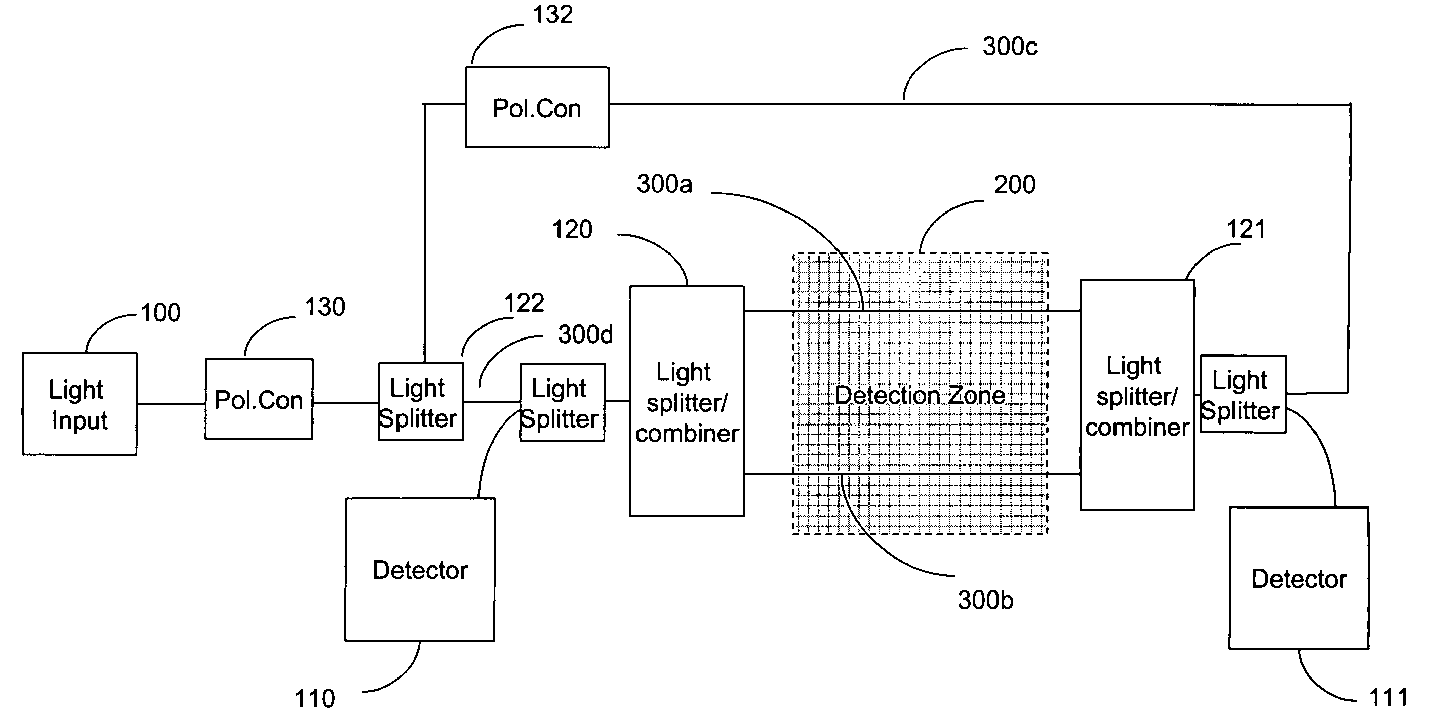
[0045] The invention manages variations in polarization aspects of two or more light signals, in a system that uses interference between the light beams for counter-propagating light signals in discerning the location along an extended waveguide at which a detectable occurrence has disturbed the light propagation conditions for both light signals. The disturbance locally affects two counter-propagating optical signals simultaneously, but is detected after the affected light beams have propagated along paths of different length.

[0046] Corresponding signal variations are received from the two signals at different times due to the different path lengths. These variations comprise intensity variation caused by the phase variations that result from a disturbance-induced change in optical propagation conditions. According to the invention, the received signals are combined in a polarization insensitive way, by controlling the polarization state of the input beams. In this way, the time d...


PUM


Abstract

Polarization effects are managed to provide differential timing information for localizing disturbances affecting two or more counter-propagating light signals on one or more optical waveguides passing through a detection zone. Activity can be localized to a point for a security perimeter. Events causing optical disturbance can be mapped to points along a straight line, a perimeter or arbitrary pattern or an array. Events cause local changes in optical properties in the optical waveguide, in particular an optical fiber. Short term local changes are distinguishable from phase changes of light travel in the waveguide by managing the polarization state of input and output beams.

Description

CROSS REFERENCE TO RELATED APPLICATIONS [0001] This application claims the priority of U.S. Provisional Patent Applications Ser. No. 60 / 534,264, filed Jan. 5, 2004; Ser. No. 60 / 542,005, filed Feb. 5, 2004; Ser. No. 60 / 555,163, filed Mar. 22, 2004; Ser. No. 60 / 556,979, filed Mar. 26, 2004; Ser. No. 60 / 572,169, filed May 18, 2004; and Ser. No. 60 / 576,434, filed Jun. 3, 2004.BACKGROUND OF THE INVENTION [0002] 1. Field of the Invention [0003] The invention concerns a detection and locating apparatus and method using an optical fiber or similar waveguide as a distributed sensor by which a disturbance can be sensed and its location determined to a point along the path of the optical fiber. According to an inventive aspect, polarization effects managed to make such detection dependable notwithstanding changing conditions, and to provide a robust ratio of signal to noise. [0004] In one embodiment, two light signals are developed and coupled into two counter-propagating light signal channels...

Claims


Application Information

Patent Timeline
IPC IPC(8): G01L1/24G08B13/12G08B13/186
CPCG01L1/242G08B13/186G08B13/124G01M11/39
Inventor PATEL, JAYANTILAL S.ZHUANG, ZHIZHONGZADOROZHNY, YURI
Owner FUTURE FIBRE TECH PTY LTD
Why Eureka
Try Eureka