Markers for visualizing interventional medical devices

a medical device and visualization technology, applied in the field of visualizing interventional medical devices, can solve the problems of iodinated contrast agents with real incidence of acute renal failure, systemic administration of contrast agents that would require too high doses of agents, and the use of fluoroscopy ionizing x-ray radiation with its attendant hazards

Inactive Publication Date: 2005-07-07
BIOPHAN TECH
View PDF99 Cites 138 Cited by
  • Summary
  • Abstract
  • Description
  • Claims
  • Application Information

AI Technical Summary

Benefits of technology

[0047]FIG. 33 is a schematic of a device for testing the degree to which the Farad

Problems solved by technology

As good as fluoroscopy is, however, it does have drawbacks.
Systemic administration of the contrast agent would require too high a dose of agent.
Additionally, iodinated contrast agents are nephrotoxic with a real incidence of acute renal failure, particularly in patients with compromised renal function.
Moreover, fluoroscopy uses ionizing x-ray radiation with its attendant hazards.
This is an issue f

Method used


Image

  • Markers for visualizing interventional medical devices
  • Markers for visualizing interventional medical devices
  • Markers for visualizing interventional medical devices

Examples


Embodiment Construction

Nanomagnetic Embodiment of the Invention

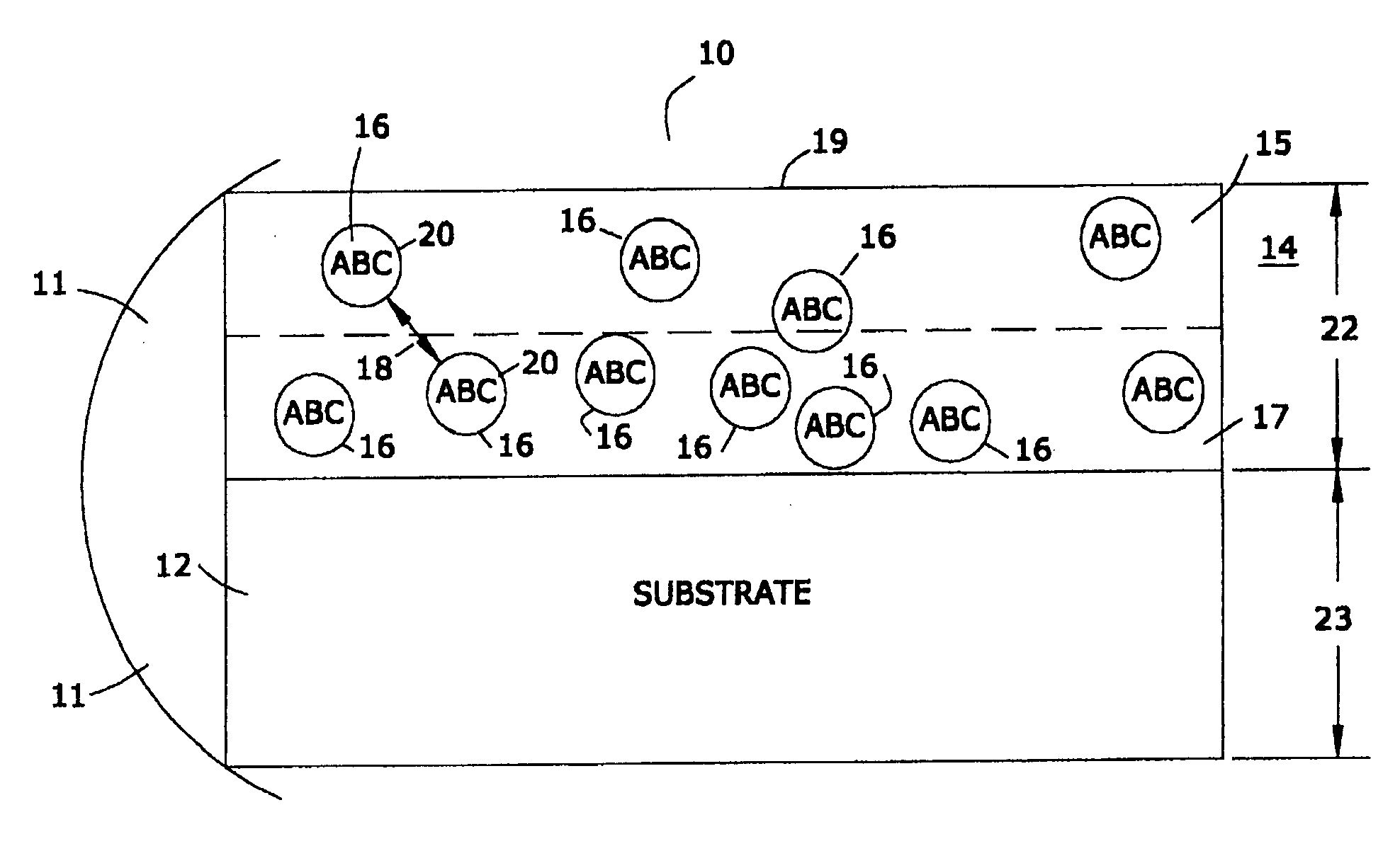
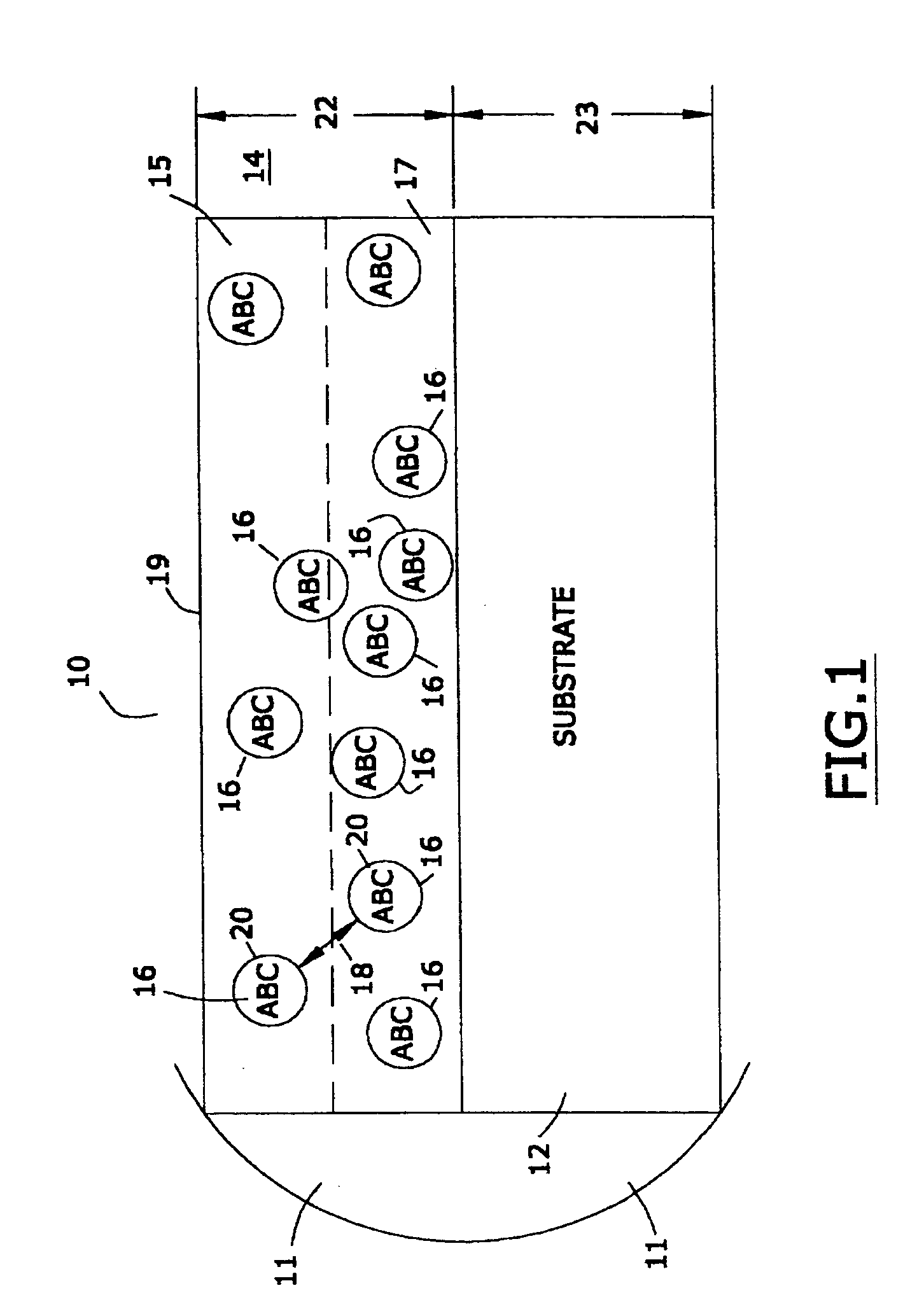
[0049] In one embodiment of this invention, the marker material is comprised of a nanomagnetic material such as has been described by applicants in several of their prior United States patents. Reference may be had, e.g., to U.S. Pat. No. 6,506,972 (magnetically shielded conductor), U.S. Pat. No. 6,673,999 (magnetically shielded assembly), U.S. Pat. No. 6,700,472 (magnetic thin film inductors), U.S. Pat. No. 6,713,671 (magnetically shielded assembly), and U.S. Pat. No. 6,765,144 (magnetic resonance imaging coated assembly). The entire disclosure of each of these United States patents, especially as it relates to nanomagnetic material, is hereby incorporated by reference into this specification.

[0050] In one embodiment the magnetic permeability of the particulate material is greater than the magnetic permeability of the matrix material, being at least 1.000005 to 20,000 times as great. As used in this specification, the term “magnetic permea...


PUM


Abstract

A marking material that, when disposed upon medical devices used during interventional medical procedures with imaging modalities such as X-ray Fluoroscopy and Magnetic Resonance Imaging, renders such medical devices visible with minimal imaging artifacts. The material comprises a particulate material with generally higher atomic weight disposed within a matrix material with generally lower atomic weight. In one embodiment the particulate material is magnetic. In another embodiment the particulate material is non-magnetic.

Description

CROSS-REFERENCE TO RELATED PATENT APPLICATIONS [0001] This application is a continuation-in-part of applicants' U.S. patent application Ser. No. 10 / 974,412, file on Oct. 27, 2004, which in turn was a continuation-in-part of applicants' U.S. patent application Ser. No. 10 / 950,148, filed on Sep. 24, 2004, which in turn was a continuation-in-part of applicants' patent application Ser. No. 10 / 923,579, filed on Aug. 20, 2004, which in turn was a continuation-in-part of each of applicants' copending patent application Ser. No. 10 / 914,691 (filed on Aug. 8, 2004), Ser. No. 10 / 887,521 (filed on Jul. 7, 2004), Ser. No. 10,867,517 (filed on Jun. 14, 2004), Ser. No. 10 / 810,916 (filed on Mar. 26, 2004), Ser. No. 10 / 808,618 (filed on Mar. 24, 2004), Ser. No. 10 / 786,198 (filed on Feb. 25, 2004), Ser. No. 10 / 780,045 (filed on Feb. 17, 2004), Ser. No. 10 / 747,472 (filed on Dec. 29, 2003), Ser. No. 10 / 744,543 (fled on Dec. 22, 2003), Ser. No. 10 / 442,420 (filed on May 21, 2003), and Ser. No. 10 / 409,505...

Claims


Application Information

Patent Timeline
IPC IPC(8): A61B17/00
CPCA61F2250/0045A61F2250/0098A61L29/18A61B2019/5466A61F2/82A61B19/54A61B2017/00831A61L31/18A61B90/39A61B2090/3966
Inventor WANG, XINGWUSHELLOCK, FRANK G.
Owner BIOPHAN TECH
Why Eureka
Try Eureka