Enhanced device for diminishing or eliminating the pain caused by superficial therapeutic injection or superficial body tissue sampling or the pain from a superficial injury as well as for the reduction of hemorrhage from an injured area

a technology of enhanced devices and injections, applied in the field of therapeutic injections, can solve the problems of electrodes used, difficulty or inability to recognize the timing of sharp sensations, type of tens generating and control units, etc., and achieve the effect of reducing or eliminating pain on skin breach, reducing the tendency for deeper and wider tissue stimulation, and reducing overall signal strength

Inactive Publication Date: 2005-07-07
CLINIWAVE
View PDF24 Cites 17 Cited by
  • Summary
  • Abstract
  • Description
  • Claims
  • Application Information

AI Technical Summary

Benefits of technology

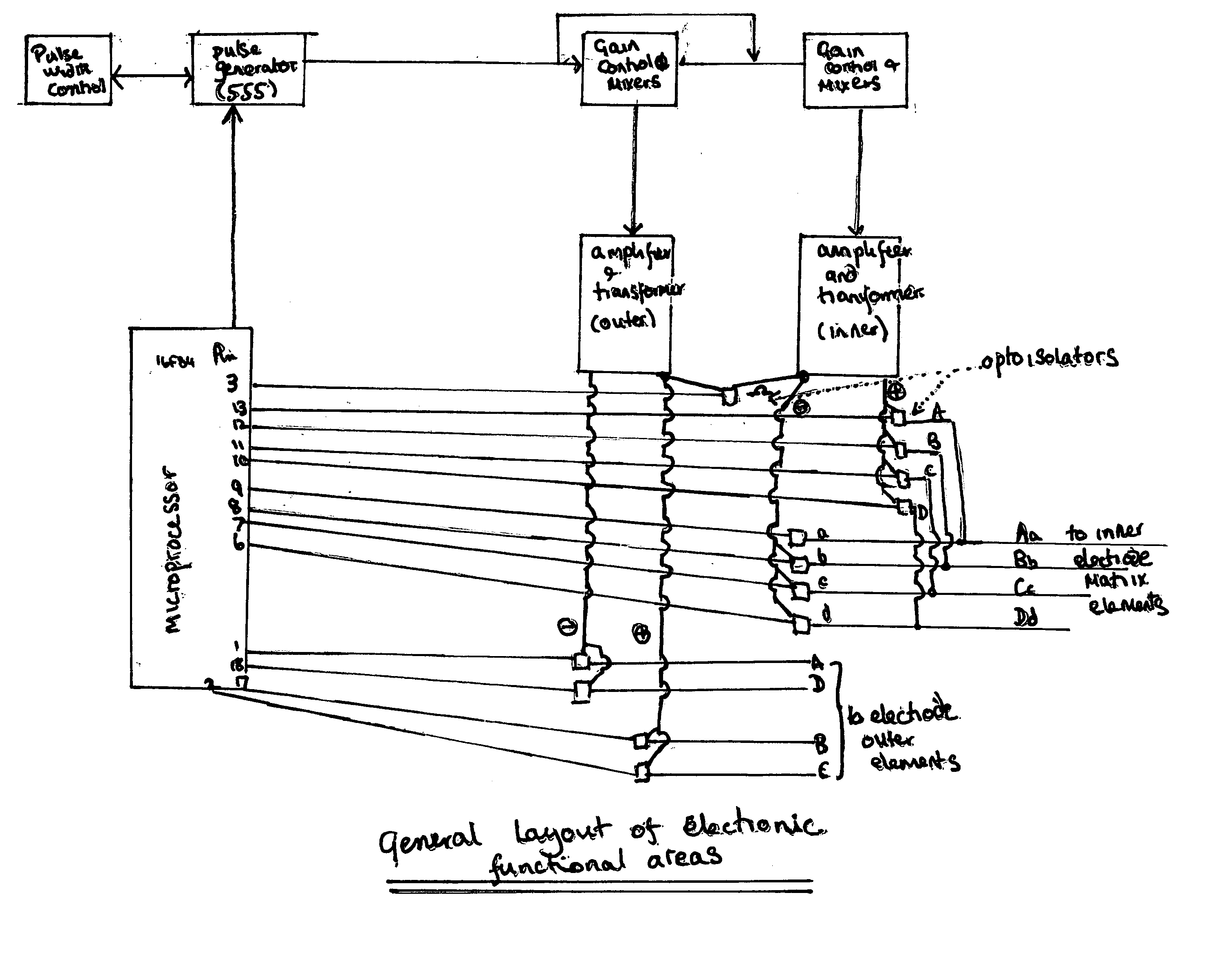
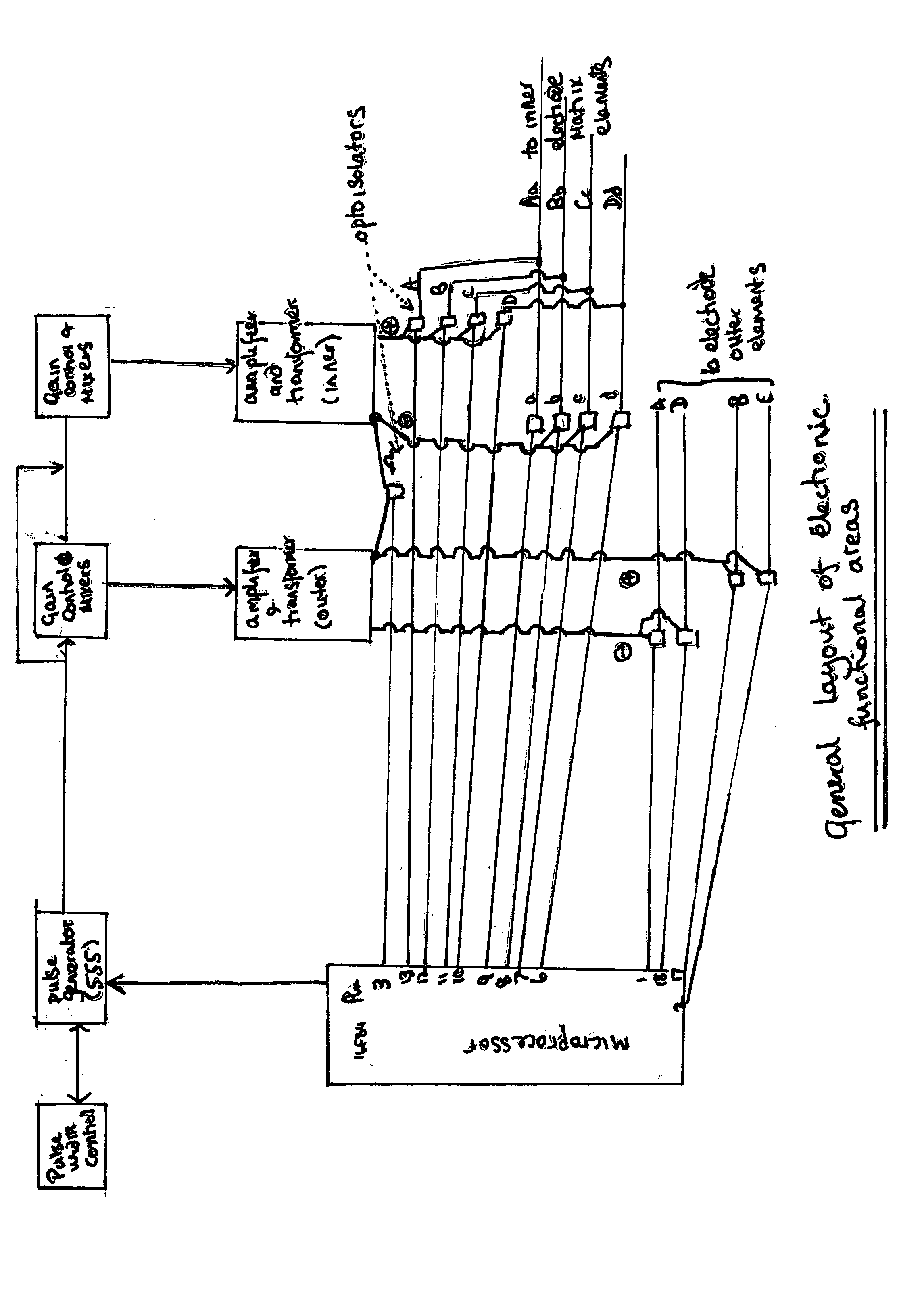
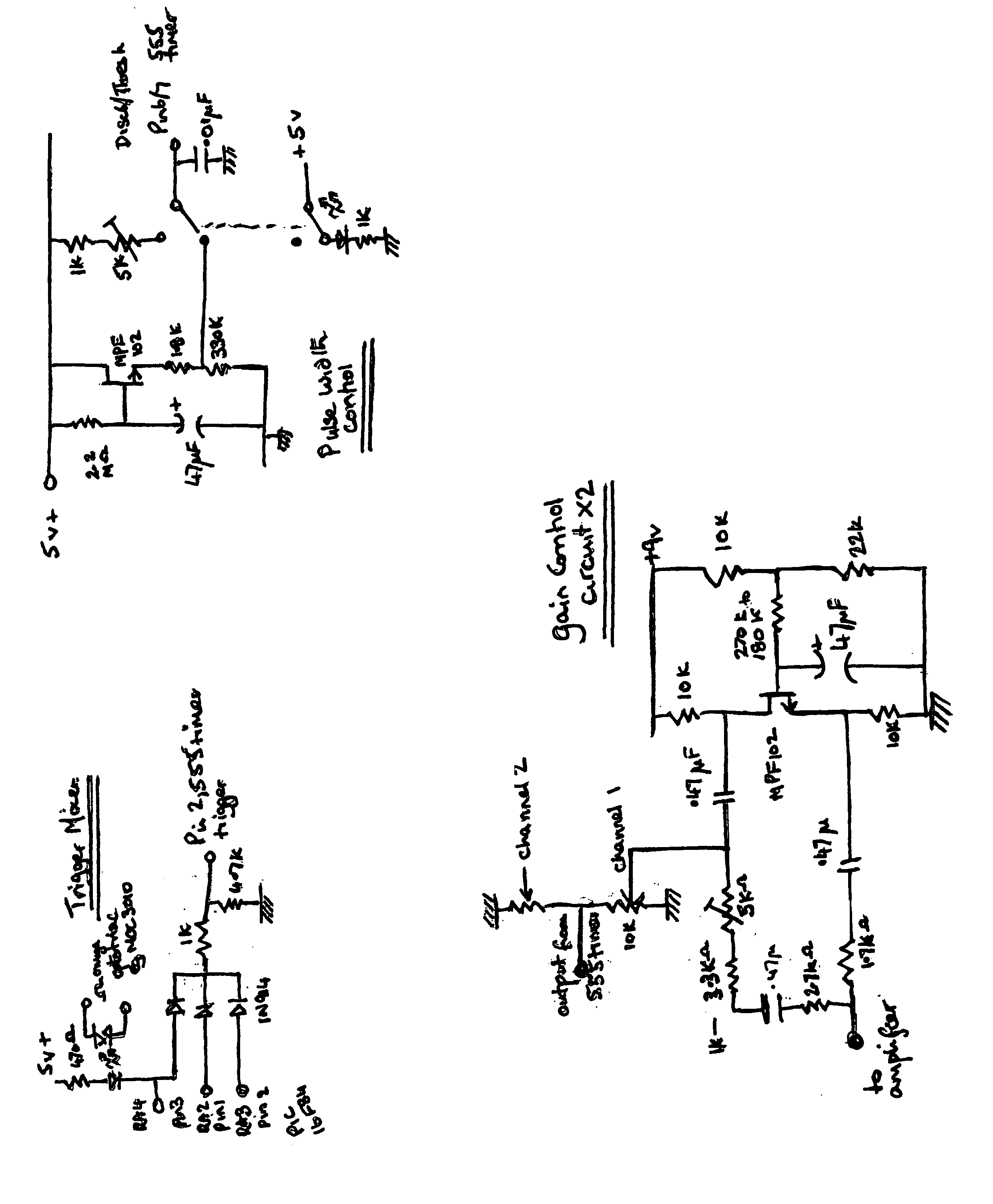
[0005] This invention provides a means of reducing or eliminating pain on skin breach such as during a therapeutic injection, by the application of TENS (trans-epithelial nerve stimulation) with or without a co stimulus of vibration before during and after an injection. The method is also applicable for superficial pain relief or hemorrhage as may be useful in the management of a surgical or other wounds. The beneficial effect is achieved through the use of an electrode array, which meets certain defined specifications in the size and arrangement of electrode elements, in association with a control unit, that switches TENS signals between these various electrode elements in a specified manner. By this means the locality of the TENS current can be controlled and differing nerve fibers can be independently targeted. The pattern of electrode activity is such that the total exposure area may have different signal patterns applied within different regions of this total exposure area. In general an inner area (proximal to the site of skin breach) has an applied pattern of TENS activity of a regular or more usually an irregular spacing between pulses, both in time and the specific route of electrical discharge. The time interval between individual pulses in this electrode area is generally a matter of a few milliseconds (though may be longer), whereas full coverage of the anatomy of this inner electrode area by a TENS signal takes a few tenths or hundredths of seconds. A second area, more peripheral to the site of injection or tissue damage, has a pulse pattern which may be regular or more usually irregular with inter-pulse pauses that may vary up to a few tenths of a second. This latter area is less demanding in the specifications required of TENS application, excepting the pulse interval pattern. The latter pattern of pulses may be added to or superimposed on the inner electrode elements in addition to their own blocking pattern, but a higher intensity is required where the two signals overlap. The effect of the outer element signal pattern, or its overlay on the inner electrode elements, is such that a sensation of irregular or patterned buzzing or prickling is noted by the recipient. This sharp irregular sensation makes it difficult or impossible to recognize the timing of the sharp sensation that is produced when a sharp instrument (needle) contacts the skin. This sensation is one of the key elements in the normal perception of pain during an injection and its disruption contributes to the efficacy of this system. The two electrode areas may intermittently have pulses applied between individual electrode elements of each area, though for the most part they are independently active and thus may both be energized as separate circuits at the same time. When both areas are energized at the same time in effect the overall signal strength may be double at that instant. The current general designs of the signal application electrodes used for TENS as well as the type of TENS generating and control units are inappropriate for this end. Rather they are better adapted to wider and deeper signal penetration utilizing electrodes of a larger area and with fewer electrode elements capable of being exposed to different signals. The preferred electrodes are arranged such that the gaps or spacing between opposite conducting electrode edges in the region of skin puncture are kept within an order of magnitude of the dimensions of skin (epidermal thickness usually being about 0.2 millimeters). Thus the electrode to electrode elements gap in the region of and adjacent to skin puncture is expected to be of the order of a millimeter or so, except where needle dimensions allow for less, or require a greater gap, such as for an intra-vascular cannula insertion. In the situation where a larger space is required for the injection (for example a cannula insertion) inter-electrode gap is kept to a minimum by employing additional electrode elements wherever possible within the inner encircling ring that circumscribes the area of skin puncture. This inner electrode arrangement affords more anatomically controlled and exact local TENS exposure of the epidermal and dermal nerve fibers, particularly C fibers which have terminals located in the epidermis as well as in deeper layers. In addition the deeper sited nerve fibers may be interacted with by these electrodes and the more widely spaced electrode combinations, switching of the TENS signal between individual and multiple electrode surfaces of the overall electrode matrix in rapid succession. Further, in addition to the gap between electrode elements, individual electrode element surface area is small (2-5 square millimeters or less), particularly those most proximal to the injection site. This further aids the localization of current flow, reducing the tendency for deeper and wider tissue stimulation as may be seen by the muscle stimulation that occurs with prevalent electrode arrangements with larger surface areas active at any one instant. The total area of tissue exposure is widened by switching activity in electrode pairs in a rapid sequential manner across the total electrode matrix area. By so doing, the area active at any one instant is small yet coverage of the total area requiring TENS exposure is effected. The TENS signals are applied across this array of electrodes and are varied in polarity, voltage, frequency, wave form and timing of application.
[0006] Different anatomical locations on the body require different settings for maximum effect and comfort. Within the locale of the electrode matrix, different electrode pairs or combinations may be concurrently targeted for either nerve blockade or counter irritation nerve stimulation causing a distraction signal to the patient. In areas less proximal to the site of skin puncture, the objective of TENS application is to produce counter irritation or a distracting signal, blockade being a secondary objective. The peripheral (distracting) signal also allows the centrally located electrode surfaces to deliver a higher strength of signal than would otherwise be comfortable, to a degree masking the more tonic sensation created by the signals applied to these electrode elements. The outer element function requires a less exacting specification for current application depth and therefore electrode size and geometry may be larger and more separated. The TENS signal waveform applied may be a standard repetitive uni- or bipolar pulse (either in a prolonged series or in bursts), as in the ordinary use of TENS. Mote complex wave forms may be used, such as described in U.S. Pat. No. 4,723,552. This latter may allow for the tuning of the TENS current to the characteristics of the nerve and nerve endings targeted, reducing the tendency of spread and allowing a lower power TENS signal to be effective. However, with the present arrangement a simple unidirectional pulse is effective, when applied in the fashion described below, particularly noting the frequency and irregularity off pulse intervals between pulses as they are applied through the two electrode areas. The provision of a concurrent physical vibration to the device and / or skin both reduces the direct force and energy required for needle penetration (which is related to the perception of pain severity) as well as providing an additional distracting stimulus to the patient and consequent masking of pain perception. Using the same principles of an inner and outer electrode element matrix the electrode may be fashioned into a wound dressing or the electrode array may be fashioned so as to allow biopsy or other surgical device use. In these cases and uses, the smaller and more closely spaced electrode elements are most proximal to the area of tissue injury. Further, as a consequence of vascular smooth muscle contraction resulting either directly or through reflex to the local application of an intense TENS current, hemorrhage my be diminished or eliminated.

Problems solved by technology

This sharp irregular sensation makes it difficult or impossible to recognize the timing of the sharp sensation that is produced when a sharp instrument (needle) contacts the skin.
This sensation is one of the key elements in the normal perception of pain during an injection and its disruption contributes to the efficacy of this system.
The current general designs of the signal application electrodes used for TENS as well as the type of TENS generating and control units are inappropriate for this end.
However, with the present arrangement a simple unidirectional pulse is effective, when applied in the fashion described below, particularly noting the frequency and irregularity off pulse intervals between pulses as they are applied through the two electrode areas.

Method used


Image

  • Enhanced device for diminishing or eliminating the pain caused by superficial therapeutic injection or superficial body tissue sampling or the pain from a superficial injury as well as for the reduction of hemorrhage from an injured area
  • Enhanced device for diminishing or eliminating the pain caused by superficial therapeutic injection or superficial body tissue sampling or the pain from a superficial injury as well as for the reduction of hemorrhage from an injured area
  • Enhanced device for diminishing or eliminating the pain caused by superficial therapeutic injection or superficial body tissue sampling or the pain from a superficial injury as well as for the reduction of hemorrhage from an injured area

Examples


Embodiment Construction

[0012] The over arching strategy employed in this invention rests on two main insights. First the current embodiments of TENS device are not optimized for the anatomical location of nerves within the skin or the local intensity of exposure required for significant local blockade.

[0013] Secondly, nature builds in a great deal of redundancy in all its systems including to communication. For example in written communication the well known sentence “if u cn rd the msg . . . ” clearly indicates the redundancy of information communicated in a correctly spelled sentence. The same strategy of reliability through the use of redundancy is true of the various biological systems of the body with generally over capacity of each system and adjunctive but none essential activity in each system. Thus the same message sent by multiple routes (nerve fibers) can accommodate some noise in each route but the combined central message arrives adequate for clear interpretation. In the peripheral nervous s...


PUM


Abstract

A device is disclosed which couples the use of Trans Epithelial Nerve Stimulation with the administration of a therapeutic injection, such as an immunization, or tissue sampling procedure such as deriving a blood sample. By such an arrangement the discomfort associated with these procedures may be considerably reduced or eliminated, thereby improving compliance with a range of medical procedures. To date TENS has not been used in such an arrangement, rather development in TENS technology has been aimed at improving its efficacy. Similarly injection technology developments have been orientated around reducing cross infection risks and accidental injury to operator or patient.

Description

CROSS REFERENCE TO RELATED APPLICATIONS [0001] Application Ser. No. 10 / 195,171 STATEMENT REGARDING FEDERALLY SPONSORED RESEARCH OR DEVELOPMENT [0002] Not Applicable REFERENCE TO A MICROFICHE APPENDIX [0003] Not Applicable BACKGROUND OF THE INVENTION [0004] Technology developments in the field of effecting a therapeutic injection, such as an immunization, or off a sampling of a body tissue, such as blood, have predominantly been orientated around the avoidance of cross contamination, accuracy of injection or avoidance of operator injury. Some diminution of pain of the recipient has often been a secondary consideration and has proved a somewhat intractable goal. This is at least in part due to some off the factors defining the likelihood and extent off pain are related to the nature of substance to be injected, site and depth of injection and the psychological expectation of pain by the patient. For the most part the common injections performed are regarded as inducing only minor and ...

Claims


Application Information

Patent Timeline
Patent Type & Authority Applications(United States)
IPC IPC(8): A61N1/34A61N1/36
CPCA61M5/422A61N1/0456A61N1/36021
Inventor COULTER, GEORGE GARY
Owner CLINIWAVE
Why Eureka
Try Eureka