Magnetic recording medium and a magnetic storage apparatus

Inactive Publication Date: 2005-08-02
HITACHI GLOBAL STORAGE TECH JAPAN LTD
View PDF13 Cites 4 Cited by
  • Summary
  • Abstract
  • Description
  • Claims
  • Application Information

AI Technical Summary

Benefits of technology

[0033]The purpose of forming the under layer is to adhere the substrate to the film formed on the substrate, to control the crystal orientation of the magnetic layer and the crystal grains not too small and to prevent to come the impurity gas into the magnetic layer.
[0034]The magnetic recording medium can be formed roughness on the surface and underlayer with island like roughness to improve the contact start stop characteristics (the CSS characteristics).
[0035]Furthermore, to get the magnetic recording medium with the high reliability and high recording density, a carbon layer can be formed to 3 nm˜20 nm thickness as a protective layer to the magnetism layer and a lubricant layer such as a pa

Problems solved by technology

But the coercive force obtained from this Granular medium is not sufficient for the high density recording over square inch 5 gigabits.
So, good record and reproduction characteristic can not been obtained because of reproduction output is low in recording at

Method used


Image

  • Magnetic recording medium and a magnetic storage apparatus
  • Magnetic recording medium and a magnetic storage apparatus
  • Magnetic recording medium and a magnetic storage apparatus

Examples


embodiment 1

[0094]Using the equipment equal to practical embodiment 1, V underlayer with thickness of 20 nm, (Co-15 at % Sm)-20 at % Ag magnetic layer of 14 nm, carbon protective layer of 6 nm are formed in order on chemical strengthening glass substrates. After V underlayer is formed, the substrate and the underlayer is heated to 150° C. by the lamp heater.

[0095]The formation of the magnetic layer is proceeded by placing Sm chip and Ag chip on the Co target, and the composition of the magnetic layer is controlled by the number of Sm chip and Ag chip. The substrate is rotated at 10˜30 rpm. The shutter is closed during the deposition of the magnetic layer as mentioned in the embodiment 1. All of the layer is deposited in the mixed gas atmosphere of 20% nitrogen added Ar. The medium that the magnetic layer is deposited in the condition of the shutter open is also produced, as a comparison example.

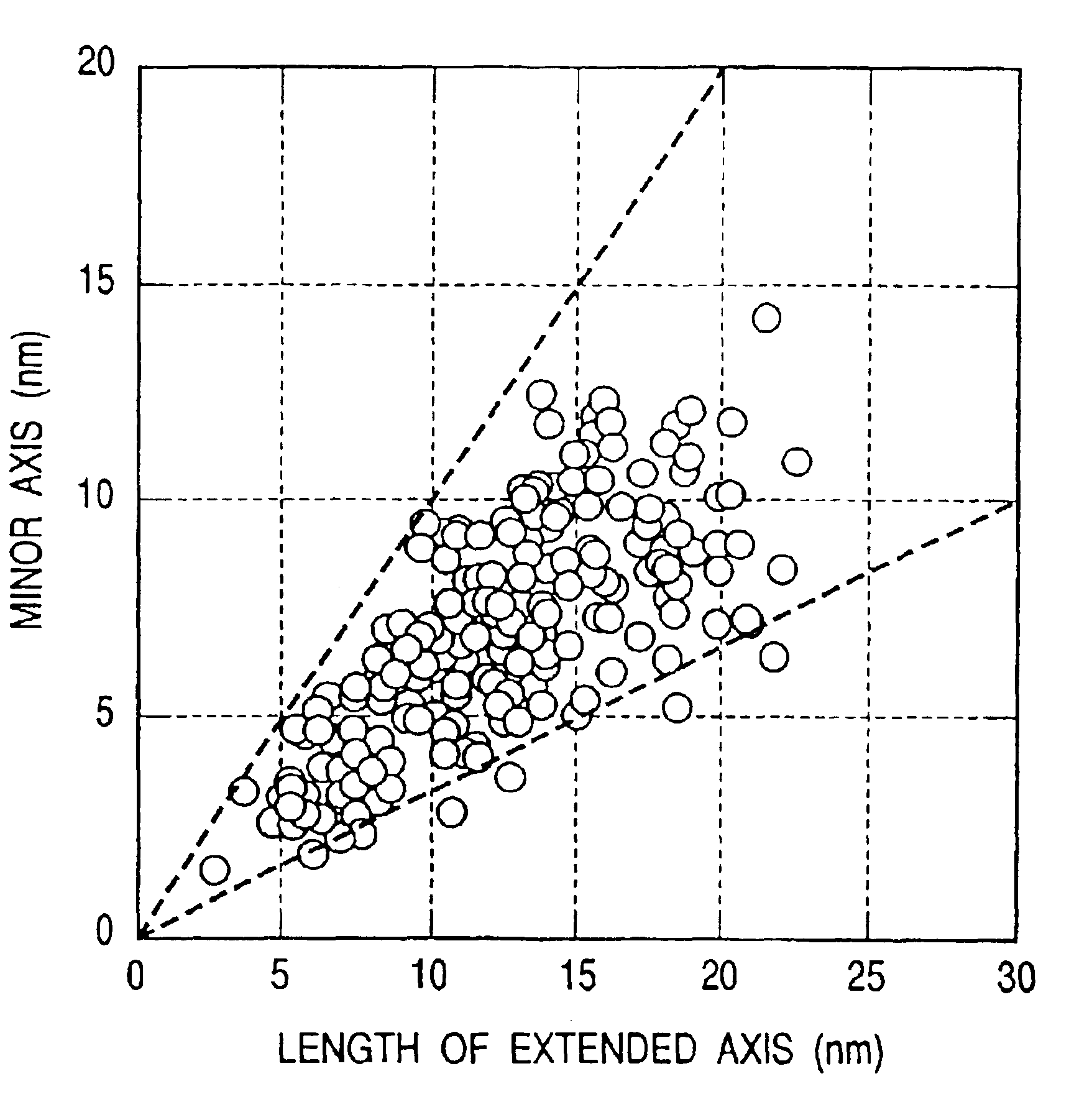
[0096]X-ray diffraction measurement is carried out on the medium of this embodiment and the medium fo...

embodiment 3

[0126]The recording and reproduction characteristic of the magnetic storage device comprising of magnetic recording medium in this embodiment and spin valve type magnetic head mention in embodiment 3 were estimated under the condition of 6 gigabits per square inch. As the result, high S / N was obtained as 2.1.

[0127]By the CSS test, the friction coefficient was under 0.2 after 30000 times CSS.

[0128]The magnetic recording medium in this invention has the effect that media noise is low, reproduction output improves in the high recording density region and the change of reproduction output is suppressed by thermomagnetic relaxation.

[0129]The magnetic storage device comprising of the magnetic recording medium in this invention and magnetoresistive head, has a recording density over 5 gigabits per square inch and does not break down over 300000 hour on average.


PUM


Abstract

A magnetic storage device has a magnetic layer, the magnetic crystal grains of which are separated by a nonmagnetic phase. The typical crystal grain is in the approximate shape of a sphere or an ellipsoid. The thickness of the magnetic crystal grains, which is in the direction perpendicular to the surface or the film, is smaller than that of the thickness of the magnetic film. The ratio of the coercive force, which is measured in the circumferential direction, to the coercive force, which is measured in the radial direction, (the orientation ratio of the coercive force), is larger than 1.0, but preferably nor greater than 3.0. Further, the area fraction of the magnetic grains having an extended axis within 30° from the circumferential direction is equal to or more than 45%.

Description

[0001]This is a continuation application of U.S. Ser. No. 09 / 343,721, filed Jun. 30, 1999, now U.S. Pat. No. 6,569,545.BACKGROUND OF THE INVENTION[0002]1. Field of the Invention[0003]This invention concerns a magnetic storage device, concretely the magnetic storage device having the recording density over 5 gigabits per square inch and the magnetic recording medium to realize the magnetic storage device having the high output, low noise and high stability caused by suppressing the attenuation of output by moderating the thermo-magnetization.[0004]2. Description of the Related Art[0005]Recently, because the recording density has been improved in the magnetic storage device for the computer, more and more noise reduction and high coercivity have been required. The minimizing the crystal grain size in the magnetic layer and the reduction of the magnetic combination of interparticles are effective for the media noise reduction. As a method for minimizing the magnetic crystal grain, form...

Claims


Application Information

Patent Timeline
IPC IPC(8): G11B5/70G11B5/714G11B5/39G11B5/64G11B5/66G11B5/65G11B5/738
CPCG11B5/70G11B5/714Y10S428/90
Inventor KANBE, TETSUYAHOSOE, YUZURUTAMAI, ICHIROTAKAHASHI, YOSHIOTANAHASHI, KIWAMUMATSUNUMA, SATOSHISHIROISHI, YOSHIHIRO
Owner HITACHI GLOBAL STORAGE TECH JAPAN LTD
Why Eureka
Try Eureka