
Digital signal receiving apparatus, an optical transmission apparatus therewith, and a discriminating point control method

a digital signal and receiving apparatus technology, applied in the field of digital signal receiving apparatus, optical transmission apparatus therewith, and discriminating point control method, can solve the problems of polarization dispersion compensating unit b>4/b>, limited transmission distance, and degradation of optical signal waveform, etc., to achieve the effect of small size and economic

Inactive Publication Date: 2005-07-07
FUJITSU LTD
View PDF4 Cites 6 Cited by
  • Summary
  • Abstract
  • Description
  • Claims
  • Application Information

AI Technical Summary

Benefits of technology

[0016] A specific object of the present invention is to provide a digital signal receiving apparatus, an optical transmission apparatus that includes the digital signal receiving apparatus, and a discriminating point control method that can be constituted small and made economically.

Problems solved by technology

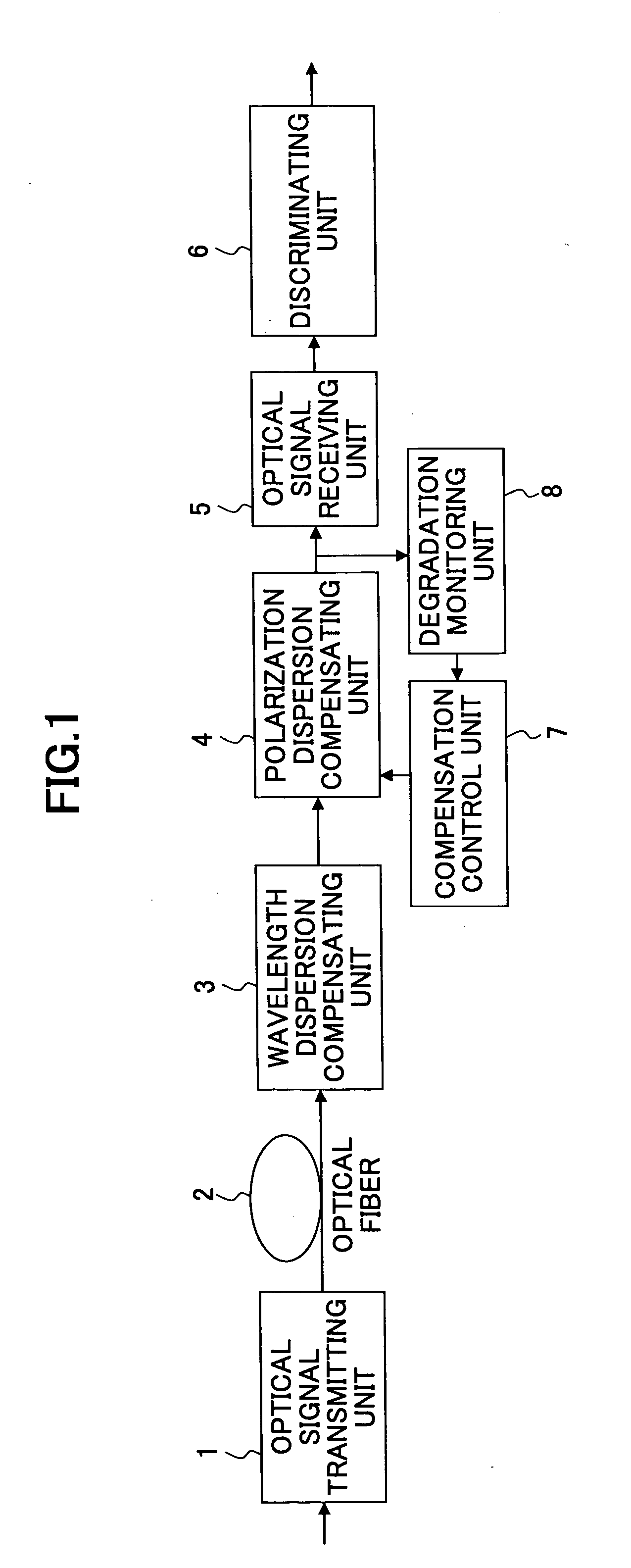
As the transmission distance of the optical transmission apparatus capable of 40 Gbps is getting longer and longer with the ever-increasing transmission speed, degradation of an optical signal waveform due to polarization dispersion through an optical fiber becomes remarkable, and poses a problem in that the transmission distance is restricted.
As described above, although the conventional system shown in FIG. 1 is capable of compensating for polarization dispersion at a high speed, a problem is that the polarization dispersion compensating unit 4, the compensation control unit 7, and the degradation monitoring unit 8, which are constituted by optical components, cannot be miniaturized, and cannot be economically built.
Generally, the conventional control systems evaluate bit errors under conditions where a bit error rate is low, taking a long time.
On the other hand, the waveform distortion due to the polarization dispersion often produces a high-speed wave change.
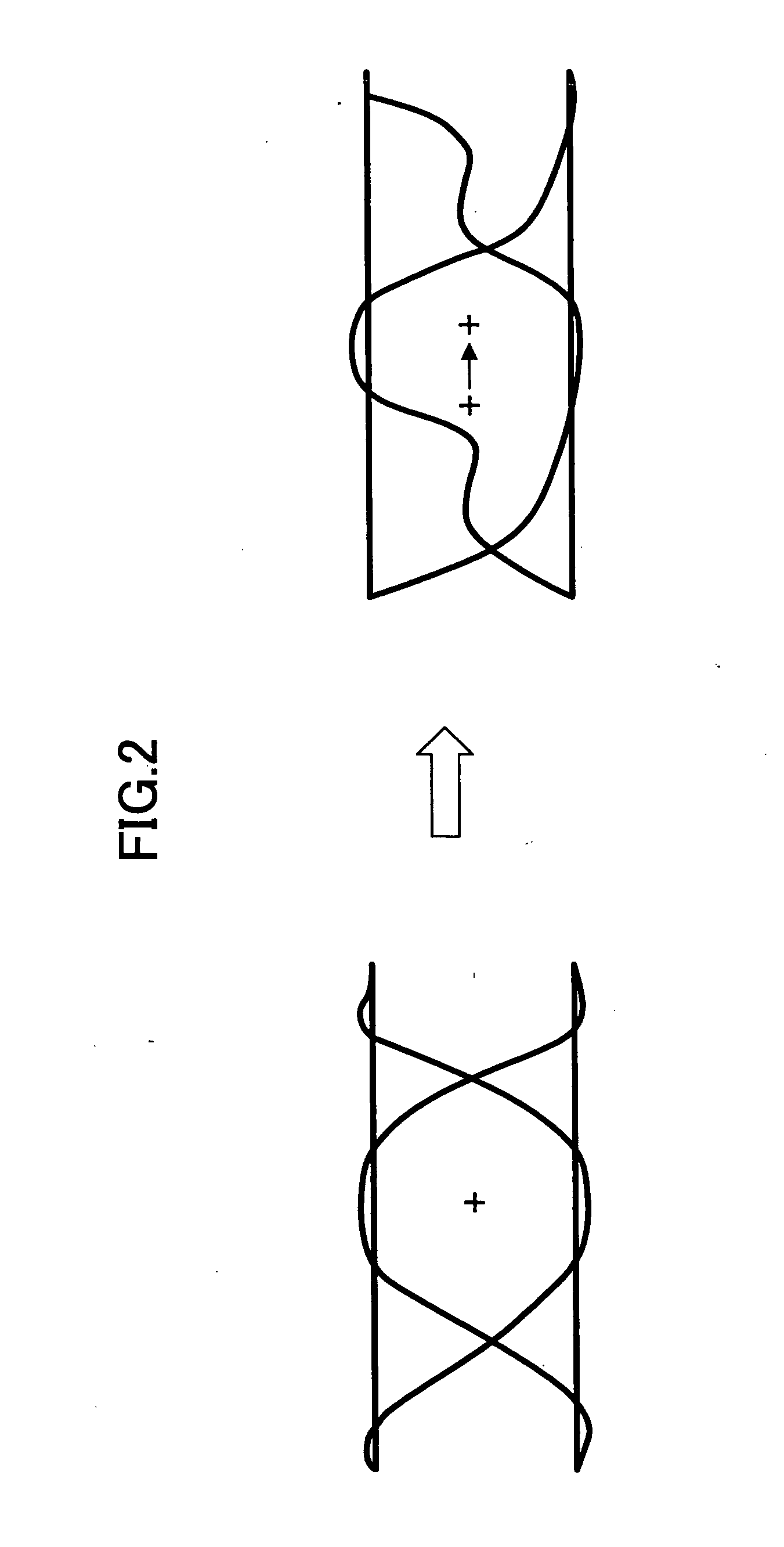
The conventional optimal control of the discriminating point by electrically monitoring the bit error rate is of a low speed, and cannot swiftly compensate for the degradation due to the polarization dispersion.

Method used


Image

  • Digital signal receiving apparatus, an optical transmission apparatus therewith, and a discriminating point control method
  • Digital signal receiving apparatus, an optical transmission apparatus therewith, and a discriminating point control method
  • Digital signal receiving apparatus, an optical transmission apparatus therewith, and a discriminating point control method

Examples


first embodiment

[0034]FIG. 3 is a block diagram of the present invention. The system shown in FIG. 3 includes an optical signal transmitting unit 1, an optical fiber 2, a wavelength dispersion compensating unit 3, an optical signal receiving unit 11, a main signal discriminating unit 12, an error correction unit 13, a discriminating point control unit 14, a monitor signal discriminating unit 15, and a error monitoring unit 16.

[0035] Here, the optical signal receiving unit 11, the main signal discriminating unit 12, the error correction unit 13, the discriminating point control unit 14, the monitor signal discriminating unit 15, and the error monitoring unit 16 constitute a digital signal receiving apparatus.

[0036] The main signal discriminating unit 12, the error correction unit 13, the discriminating point control unit 14, the monitor signal discriminating unit 15, and the error monitoring unit 16 are units that handle electrical signals, replacing the polarization dispersion compensating unit 4,...

second embodiment

[0054]FIG. 5 is a block diagram of the present invention. The system in FIG. 5 includes the optical signal transmitting unit 1, the optical fiber 2, the wavelength dispersion compensating unit 3, the optical signal receiving unit 11, the main signal discriminating unit 12, the error correction unit 13, a discriminating point control unit 24, the monitor signal discriminating unit 15, a error monitoring unit 16, and a discriminating point load unit 27.

[0055] Here, the optical signal receiving unit 11, the main signal discriminating unit 12, the error correction unit 13, the discriminating point control unit 24, the monitor signal discriminating unit 15, the error monitoring unit 16, and the discriminating point load unit 27 constitute a digital signal receiving apparatus.

[0056] The main signal discriminating unit 12, the error correction unit 13, the discriminating point control unit 24, the monitor signal discriminating unit 15, the error monitoring unit 16, and the discriminating ...

third embodiment

[0068]FIG. 8 is a block diagram of the present invention. The system shown in FIG. 5 includes the optical signal transmitting unit 1, the optical fiber 2, the wavelength dispersion compensating unit 3, the optical signal receiving unit 11, the main signal discriminating unit 12, the error correction unit 13, the error monitoring unit 16, a discriminating point control unit 34, a monitor signal discriminating unit 35, and a error monitoring unit 38.

[0069] Here, the optical signal receiving unit 11, the main signal discriminating unit 12, the error correction unit 13, the error monitoring unit 16, the discriminating point control unit 34, the monitor signal discriminating unit 35, and the error monitoring unit 38 constitute a digital signal receiving apparatus.

[0070] The main signal discriminating unit 12, the error correction unit 13, the error monitoring unit 16, the discriminating point control unit 34, the monitor signal discriminating unit 35, and the error monitoring unit 38 ar...


PUM


Abstract

A digital signal receiving apparatus is disclosed. The digital signal receiving apparatus includes a main signal discriminating unit configured to discriminate a main signal of a received signal, a monitor signal discriminating unit configured to discriminate a monitor signal of the received signal, an error monitoring unit configured to monitor a discriminating error of the monitor signal discriminating unit, and a discriminating point control unit configured to control the discriminating points of the main signal discriminating unit and the monitor signal discriminating unit. The discriminating point control unit monitors an output of the error monitoring unit, moves the discriminating point of the monitor signal discriminating unit in the amplitude directions and the phase directions such that a discriminating error occurs, detects a center of discriminating points where errors are generated, and sets the detected center of the discriminating points as the discriminating point of the main signal discriminating unit.

Description

CROSS-REFERENCE TO RELATED APPLICATION [0001] This application is a U.S. continuation application filed under 35 USC 111(a) claiming benefit under 35 USC 120 and 365(c) of PCT International Application No. PCT / JP02 / 12785 filed on Dec. 5, 2002, which is hereby incorporated herein by reference.BACKGROUND OF THE INVENTION [0002] 1. Field of the Invention [0003] The present invention generally relates to a digital signal receiving apparatus, an optical transmission apparatus therewith, and a discriminating point control method; and especially relates to a digital signal receiving apparatus that has a discriminating point control unit that controls the discriminating point of a receiving signal discriminating unit, an optical transmission apparatus therewith, and a discriminating point control method of the discriminating point control unit. [0004] 2. Description of the Related Art [0005] In recent years and continuing, transmission speeds of optical transmission apparatuses are becoming...

Claims


Application Information

Patent Timeline
IPC IPC(8): G11B7/005G11B20/10H04B10/158H04B10/18
CPCG11B7/005H04B10/2569G11B20/10009
Inventor NISHIMOTO, HIROSHI
Owner FUJITSU LTD
Learn More