Integrated acoustic transducer assembly

a transducer and integrated technology, applied in the field of acoustic transducers, can solve the problems of bulky electronics packages (e.g., large preamplifier stages) being disposed elsewhere, and the sensitivity is poor

Active Publication Date: 2005-07-14
SCHLUMBERGER TECH CORP
View PDF68 Cites 45 Cited by
  • Summary
  • Abstract
  • Description
  • Claims
  • Application Information

AI Technical Summary

Problems solved by technology

Drawbacks of these conventional acoustic transducer systems include poor sensitivity and a

Method used


Image

  • Integrated acoustic transducer assembly
  • Integrated acoustic transducer assembly
  • Integrated acoustic transducer assembly

Examples


Embodiment Construction

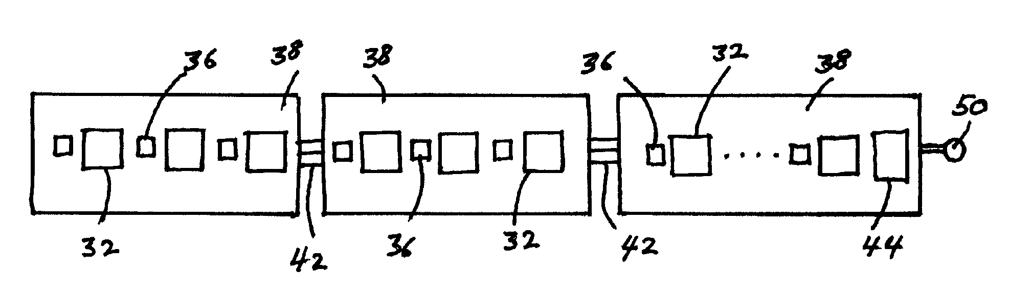
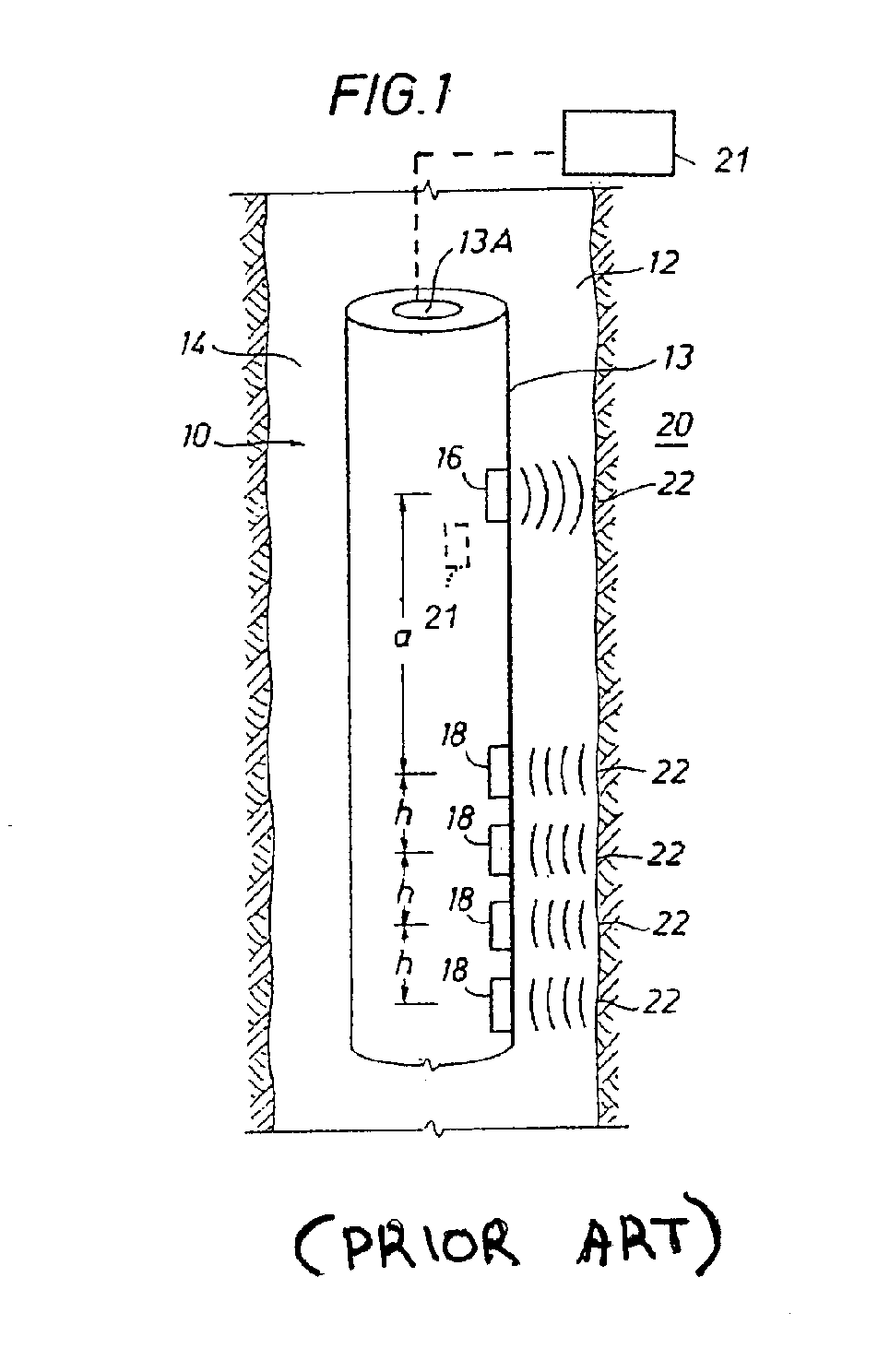
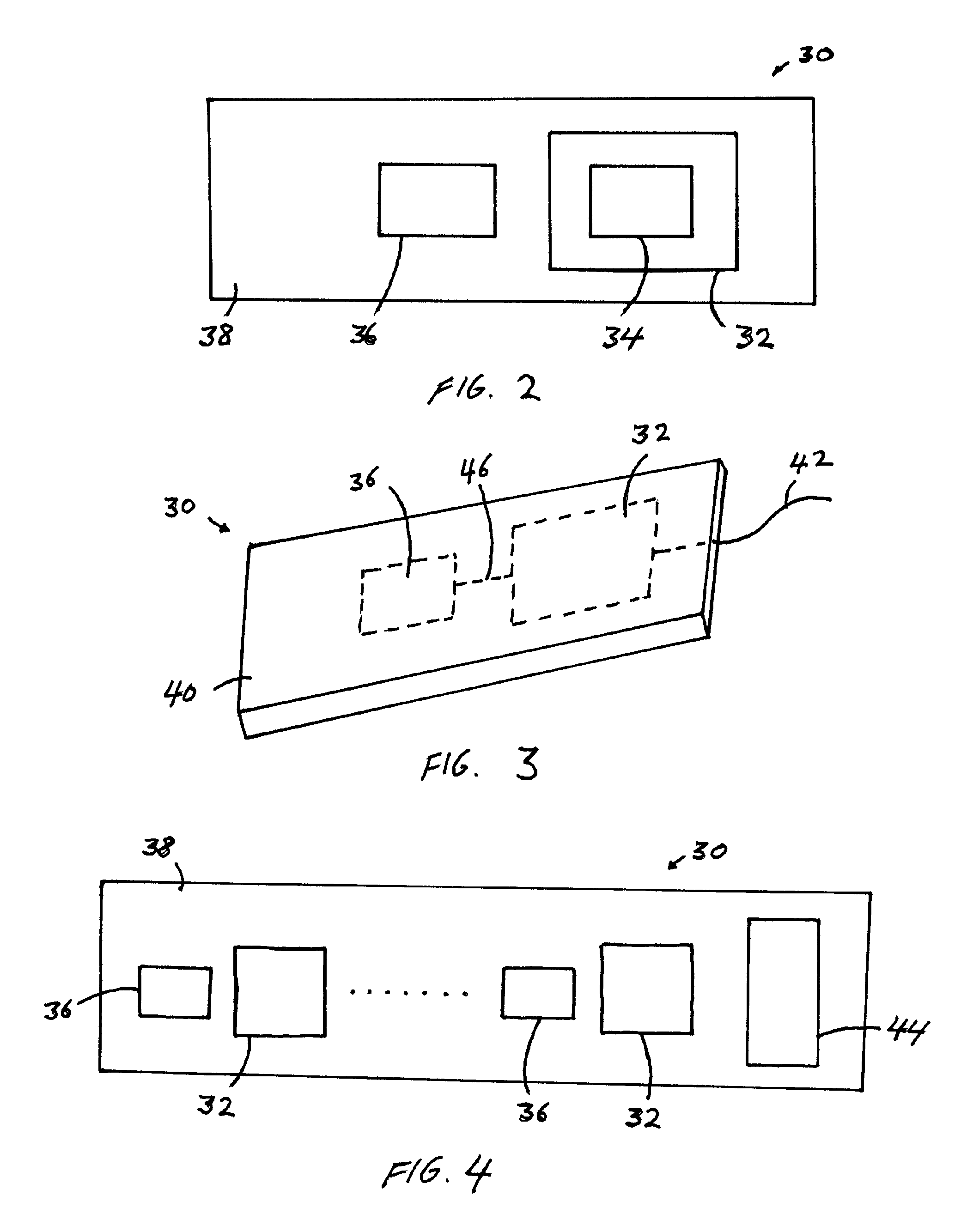
[0046] Acoustic transducers of the invention comprise electronics technology packaged such that they are suitable for exposure to harsh environments, such as a subsurface well. The transducers of the invention can be configured with a reduced number of elements and associated electronics compared to conventional designs. Circuitry is minimized and signal data are preferably digitized close to the transducer.

[0047] Transducers used as acoustic receiver arrays to measure acoustic waves in boreholes should be small and preferably individual in order to measure the acoustic wave modes propagating in the borehole such as monopole, dipole, quadrupole, and higher-order modes. Similarly these acoustic transducers should operate in different modes to reject unwanted modes. For example, in dipole or quadrupole measurements, better quality measurements may be obtained by rejecting the monopole mode. Embodiments of the invention include active sensors, with integrated electronics, that are ind...


PUM


Abstract

Acoustic transducers configured with integrated electronics technology are adapted to digitize signal data close to the transducer. The transducers are packaged with a reduced number of elements and sealed for exposure to harsh environments, without oil compensation. A transducer assembly includes a frame, an acoustic transducer element disposed on the frame, and an electronics module disposed on the frame and linked to the acoustic transducer element. The pressure and temperature tolerant electronics module is adapted to process a signal associated with the transducer element.

Description

CROSS-REFERENCE TO RELATED APPLICATIONS [0001] This invention claims priority pursuant to 35 U.S.C. § 119 of U.S. Provisional Patent Application Ser. No. 60 / 535,062, filed on Jan. 8, 2004, and U.S. Provisional Patent Application Ser. No. 60 / 534,900, filed on Jan. 8, 2004. These Provisional Applications are hereby incorporated by reference in their entirety.BACKGROUND OF INVENTION [0002] 1. Field of the Invention [0003] The invention relates generally to acoustic transducers. More particularly, this invention relates to improved acoustic sources and sensors for subsurface applications. [0004] 1. Background Art [0005] In the oil and gas industry, subsurface formations are typically probed by well logging instruments to determine the formation characteristics. Among these instruments, sonic tools have been found to provide valuable information regarding subsurface acoustic properties, which may be used to produce images or derive related characteristics for the formations. [0006] Acous...

Claims


Application Information

Patent Timeline
IPC IPC(8): E21B47/00G01C7/06E21B47/14G01NG01N29/00G01V1/00G01V1/16G01V1/40G01V1/44G01V1/52H04R1/00H04R1/02H04R3/00H04R17/02
CPCE21B47/01G01V1/44G01V1/16
Inventor GARCIA-OSUNA, FERNANDOPFUTZNER, HAROLDDUMONT, ALAINTANAKA, TETSUYA
Owner SCHLUMBERGER TECH CORP
Why Eureka
Try Eureka