Method for performing in vivo dosimetry

a detector and in vivo technology, applied in the field of in vivo dosimetry, can solve the problems of inability to control the primary tumour, occurrence of metastases, time-consuming and laborious techniques, etc., and achieve the effects of reliable dose measurement, high quality, and time-efficient and accura

Active Publication Date: 2005-07-14
NILSSON GORGEN
View PDF33 Cites 16 Cited by
  • Summary
  • Abstract
  • Description
  • Claims
  • Application Information

AI Technical Summary

Benefits of technology

[0008] The aim of the present invention is to separate the dose verification from the patient-positioning verification during Radio Therapy treatment of a patient and provide a method to perform the dose verification. The invention is thereby a method to calibrate the detectors to be used In Vivo (during treatment) in a time-efficient and accurate way to achieve high quality, reliable dose measurements during treatment.
[0017] Another alternative to measure the fluence with the detector up-streams the patient, ExtDet, is to calculate the fluence using any information of the MLC positions as input and then calibrate that fluence using the described method, eg. calibrate the fluence for each time interval to dose measured in the phantom during the pre treatment verification. Such a determination of the dose in the phantom will be limited in accuracy and verification compared to the use of an ExtDet but still very useful because it enables quantification of deviations during treatment as dose in the phantom as if it was in place.

Problems solved by technology

The major reasons for this have been the inability to control the primary tumour or the occurrence of metastases.
However when using several-fields (4-8), each field requiring individual compensators, this technique is time consuming and requires a lot of effort.
Additionally the attenuation of the beam also causes unwanted change of the spectral distribution in the beam, thereby complicating the whole process.
The new treatment technique however impose that the patient is exactly in the position expected, something not always easy to achieve.
However very little has been published on measurements during treatment, In Vivo dosimetry.
Traditional In Vivo dosimetry, measuring with a detector on the skin of the patient to predict the dose inside the patient is very demanding already with a fixed field (conventional therapy) due to limitations in the TPS (Treatment Planning System) to predict the dose distribution in the region of the patient where externally generated secondary electrons contribute significantly to the delivered dose e.g. build-up region (the part where the beam enters the patient and to a depth 5-35 mm into the patient).
Thereby neither the surface or skin dose or the dose in air up-streams the patient can be accurately predicted by the TPS in fixed fields and the difficulty increases with a dynamically delivered treatment.
In IMRT treatments it is not that easy to handle this either by general calibration or design due to the fact that the varying intensity in the field is patient specific.
The small margins in IMRT treatments require extended dosimetry and quality control also at each fraction to minimise the uncertainties and therefore the perturbation of the detectors used in conventional therapy becomes significant.
However, then the discrepancy from the predicted values will be difficult to judge due to lack of understandable quantification.
However measurement down-streams the patient alone will always be less accurate than combined with measurements up-streams the patient and will thereby not distinguish if the deviation was caused due to incorrect dose delivery by the treatment machine or due to positioning errors or change in anatomy of the patient (the patient might loose weight etc. from original diagnostics).

Method used


Image

  • Method for performing in vivo dosimetry
  • Method for performing in vivo dosimetry
  • Method for performing in vivo dosimetry

Examples


Embodiment Construction

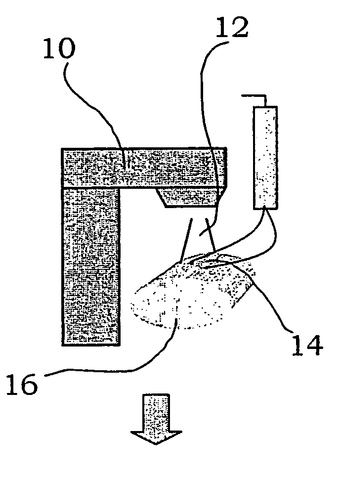
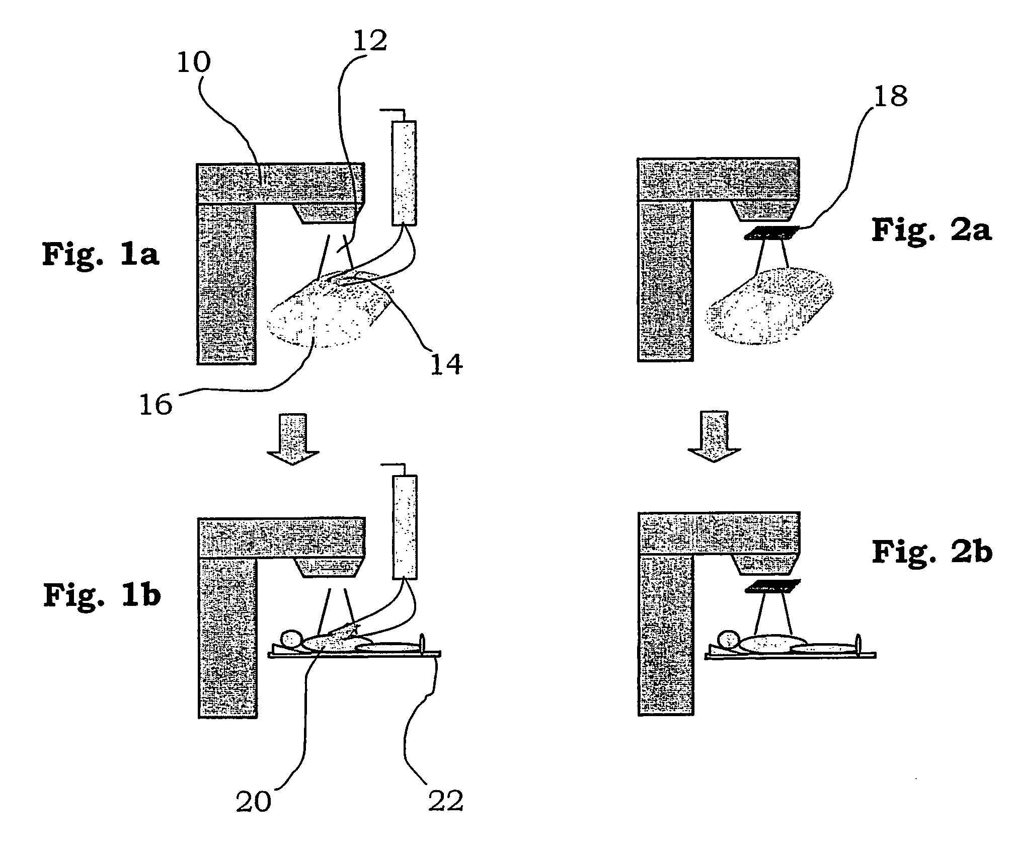
[0026] A radiotherapy device utilised for treating tumours with radiation is shown schematically in FIGS. 1-2 and is generally denoted with reference numeral 10. The device comprises a radiotherapy system capable of emitting a beam 12 of electrons or photons from a treatment head. The radiotherapy system is provided with conventional field-shaping device (not shown), for example an MLC, for allowing the lateral shape of the beam to be altered so as to shield off non-affected areas of the body and concentrate the beam to the tumour. Control means (not shown) are provided for the radiotherapy system.

[0027] A table 22 is arranged for a patient 20 to lie on. The table is rotatable around a vertical axis, and movable horizontally and vertically in order to place the area to be treated of the patient in the area of the beam. Further, the method according to the invention utilises different detectors for measuring the radiation emitted from the radiotherapy device. They may for example co...


PUM


Abstract

The present invention relates to a method enabling quantification of dose delivery in radiotherapy treatment during patient-specific treatment of the patient utilising measurements in predefined time-intervals with information means positioned in the radiation beam, between the patient and the source and converting the readings to corresponding measures in a phantom. The invention additionally covers the method to obtain the said calibration factors for the detectors. The said calibration factors are obtained for each information means, field and said definable time-interval simultaneously irradiating the information means and said phantom including detectors to measure the absorbed dose using the said patient-specific treatment without patient.

Description

TECHNICAL FIELD [0001] The present invention relates to a method for calibrating detectors intended for use in an apparatus for radiotherapy during treatment of a patient to verify the accuracy of the delivered dose to the patient. BACKGROUND OF THE INVENTION [0002] Radiotherapy has been used to treat cancer in the human body since early 1900. Even though radiation of cancer tumours is known to be efficient, mortality rate for many cancers remained virtually unchanged for a long time. The major reasons for this have been the inability to control the primary tumour or the occurrence of metastases. Only by improving the local control may the treatment be more effective. In the last years Treatment Planning Systems, TPS, in Radiation Therapy have developed extensively and is now able to take into account the anatomy of the specific patient and in a time efficient way plan a more optimised treatment for each individual patient, homogenous dose to the target and minimum dose to risk-orga...

Claims


Application Information

Patent Timeline
Patent Type & Authority Applications(United States)
IPC IPC(8): A61N5/10G21K5/02G01T1/02
CPCA61N5/1042A61N5/1071A61N5/1048A61N2005/1076
Inventor NILSSON, GORGEN
Owner NILSSON GORGEN
Why Eureka
Try Eureka