Position sensorless drive for permanent magnet synchronous motors

a synchronous motor and sensorless technology, applied in the direction of motor/generator/converter stopper, dynamo-electric gear control, dynamo-electric converter control, etc., can solve the problem of small position estimation error obtained from fusion algorithm, in the majority of cases

Active Publication Date: 2005-07-14
INFINEON TECH AMERICAS CORP
View PDF4 Cites 86 Cited by
  • Summary
  • Abstract
  • Description
  • Claims
  • Application Information

AI Technical Summary

Benefits of technology

[0006] Responsive to these issues, the present invention relates to a novel algorithm, referred to as a “fusion algorithm,” which fuses information resulting from high speed and low speed sensorless algorithms in order to estimate motor position. The fusion of the information is seamless, and the resulting estimated position is valid over the entire speed range. Experimental results show that the position estimation error obtained from this fusion algorithm is smaller, in most of the speed spectrum, than that obtained by either the low speed or the high speed algorithm alone. Furthermore, it is shown that the fusion algorithm resolves the position polarity problem, which characterizes low speed sensorless algorithms.

Problems solved by technology

Experimental results show that the position estimation error obtained from this fusion algorithm is smaller, in most of the speed spectrum, than that obtained by either the low speed or the high speed algorithm alone.

Method used


Image

  • Position sensorless drive for permanent magnet synchronous motors
  • Position sensorless drive for permanent magnet synchronous motors
  • Position sensorless drive for permanent magnet synchronous motors

Examples


Embodiment Construction

[0023] A. Mathematical Model of Motor

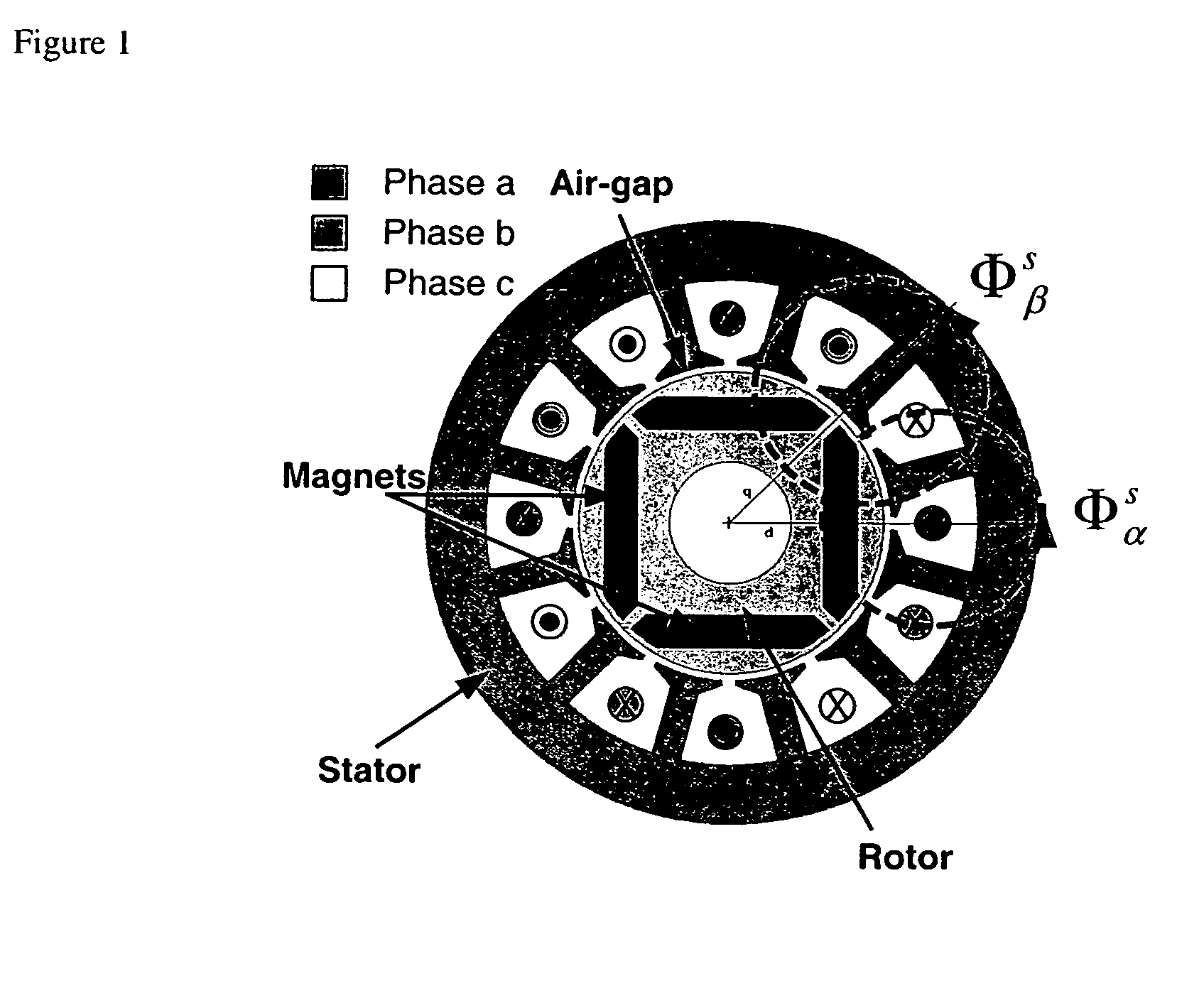
[0024] A PM motor constructed with saliency will exhibit a constant difference ΔLr between its stator inductance L observed along the d-axis and that observed along the q-axis of the rotating reference frame. In the stationary reference frame, this difference will manifest itself as a variation in L that is a function of the rotor position. This is the case for the IPM motor shown in FIG. 1, which exhibits saliency. For this IPM motor, it is evident that the flux Φαs sees less reluctance than Φβs because it flows mostly along the length of the low reluctance magnet material. The inductance Lα will therefore differ from Lβ.

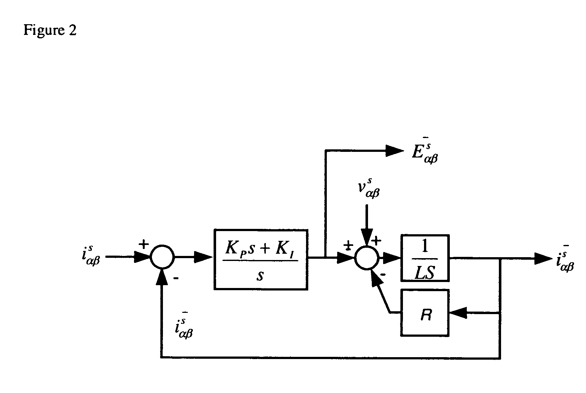
[0025] This inductance variation appears in the differential equations that govern the electrical dynamics of the motor. These are given by (1) and (2), in the rotating reference frame. Vdr=R⁢ ⁢idr+L⁢ ⁢ⅆⅆt⁢idr-L⁢ ⁢ωm⁢iqr(1)Vqr=R⁢ ⁢iqr+L⁢ ⁢ⅆⅆt⁢iqr-Δ⁢ ⁢Lr⁢ⅆⅆt⁢iqr+L⁢ ⁢ωm⁢idr+λr⁢ωm(2)

Where: [0026] Vdr and Vqr are the direct and ...


PUM


Abstract

A sensorless motor control algorithm that single-handedly permits operation over the entire speed range from low speed to high speed. This “fusion” algorithm seamlessly fuses the position data generated respectively by high speed and low speed sensorless algorithms. The resulting sensorless drive permits effective position sensorless operation over the entire speed range of a PM motor.

Description

CROSS-REFERENCE TO RELATED APPLICATIONS [0001] This application is based upon and claims priority of U.S. Provisional Application Ser. No. 60 / 536,566 filed Jan. 14, 2004, and Ser. No. 60 / 622,440 filed Oct. 27, 2004, the disclosures of which are incorporated by reference.BACKGROUND OF THE INVENTION [0002] Permanent magnet (PM) motors appear to be gaining momentum in industry. This is due to their increased efficiency and small size, which owes to the presence of a permanent magnet in the rotor. In particular, PM motors with sinusoidal back-EMF are of interest because they produce much less torque ripple than their trapezoidal back-EMF equivalents. Synchronous motors have generally included a position sensor to support position-based control algorithms. Given the apparent increasing market demand for this type of motor, the use of position sensorless technology for their control and drive implementation becomes highly valuable. In fact, the cost reduction associated with removing the ...

Claims


Application Information

Patent Timeline
Patent Type & Authority Applications(United States)
IPC IPC(8): H02P6/18H02P21/04
CPCH02P6/181H02P6/182Y10S388/911H02P2203/05H02P21/04
Inventor QUIRION, JEAN
Owner INFINEON TECH AMERICAS CORP
Why Eureka
Try Eureka