Fast wake-up crystal oscillating circuit

a crystal oscillating circuit and wake-up technology, applied in the direction of oscillating circuits, generator stabilization, electrical equipment, etc., can solve the problems of oscillating circuit amplifiers that cannot wake up at the same time, and difficulty or even failure of crystal oscillating circuits to wake up

Inactive Publication Date: 2005-07-14
SUNPLUS TECH CO LTD
View PDF2 Cites 17 Cited by
  • Summary
  • Abstract
  • Description
  • Claims
  • Application Information

AI Technical Summary

Benefits of technology

[0008] It is therefore an object of the present invention to provide a fast wake-up crystal oscillating circuit capable of assuring successful oscillation without being influenced by the manufacturing process, load capacitor and power supply variations.

Problems solved by technology

In practical applications, these variations may cause difficulty or even failure for the crystal oscillating circuit to wake up.
However, the current consumed by the amplifiers at that time is also high.
However, after wake-up, only one basic inverting amplifier 11 is retained, and thus the wake-up crystal oscillating circuit also encounters the same problem as the conventional crystal oscillating circuit in that the crystal oscillating circuit may fail to wake up due to operation voltage, processing parameter and load capacitor variations.

Method used


Image

  • Fast wake-up crystal oscillating circuit
  • Fast wake-up crystal oscillating circuit
  • Fast wake-up crystal oscillating circuit

Examples


Embodiment Construction

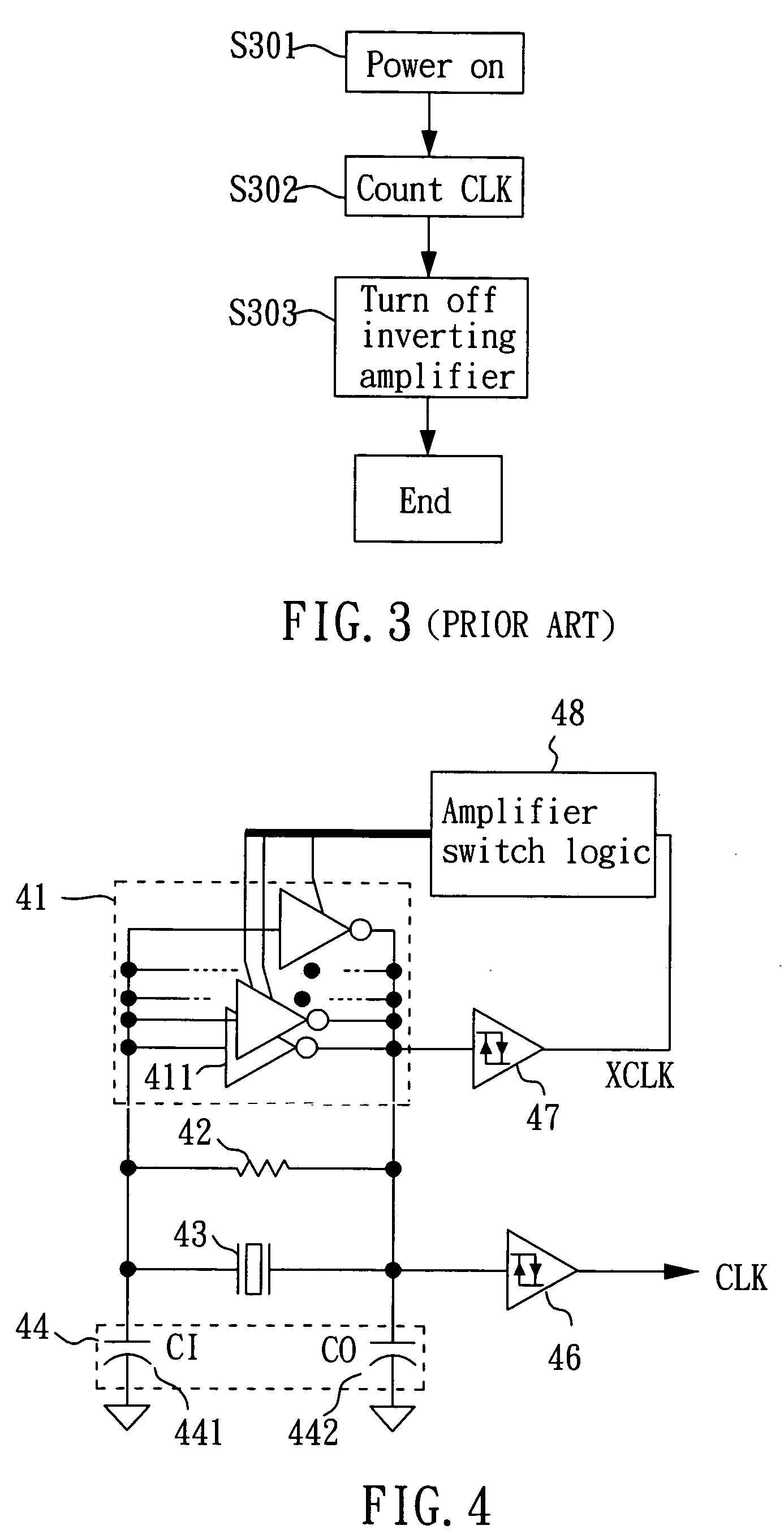
[0020]FIG. 4 is an embodiment of a fast wake-up crystal oscillating circuit in accordance with the present invention. The fast wake-up crystal oscillating circuit comprises an amplifier set 41, a feedback resistor 42, a crystal oscillator 43, a pair of capacitors 44, a first trigger 46, a second trigger 47 and an amplifier switch logic 48. The amplifier set 41 includes a number of amplifiers 411 connected in parallel for amplifying a signal to provide a gain for the crystal oscillating circuit. Preferably, the amplifiers 411 are inverting amplifiers. The feedback resistor 42 is connected in parallel with the amplifier set 41 for supplying a DC operation bias to the amplifier set 41. The crystal oscillator 43 is connected in parallel with the feedback resistor 42 and the amplifier set 41 to generate an oscillation signal having a resonance frequency. The pair of capacitors 44 has capacitors 411 and 412 respectively connected to the two terminals of the crystal oscillator 43 to cause ...


PUM


Abstract

A fast wake-up crystal oscillating circuit includes: a crystal oscillator for generating oscillation signal, an amplifier set, a feedback resistor, first and second triggers and an amplifier switch logic. The amplifier set amplifies the oscillation signal. The feedback resistor supplies DC operation bias to the amplifier set. The first trigger has an input connected to the output of the amplifier set so that the first trigger is triggered by the amplified oscillation signal to generate a first clock. The second trigger has an input connected the output of the amplifier set so that the second trigger is triggered by the amplified oscillation signal to generate a second clock, wherein the second trigger has a hysteresis voltage higher than a predetermined value. The amplifier switch logic is connected to the second trigger to gradually decrease the amplification of the amplifier set when detecting that the second trigger generates the second clock.

Description

BACKGROUND OF THE INVENTION [0001] 1. Field of the Invention [0002] The present invention relates to a crystal oscillating circuit, and more particularly to a fast wake-up crystal oscillating circuit capable of assuring successful oscillation. [0003] 2. Description of Related Art [0004]FIG. 1 shows a conventional crystal oscillating circuit comprising an inverting amplifier 11, a feedback resistor 12, a crystal oscillator 13, a pair of capacitors 14 and a Schmitt trigger 16. The inverting amplifier 11 is employed for signal amplification to provide a gain for the crystal oscillating circuit. The Schmitt trigger 16 is triggered by an amplified signal generated by the inverting amplifier 11 to output a clock signal CLK. The feedback resistor 12 supplies a DC operation bias to the inverting amplifier 11. The crystal oscillator 13 generates an oscillation signal having a resonance frequency. The pair of capacitors 14 causes the crystal oscillating circuit to have a parallel resonance ve...

Claims


Application Information

Patent Timeline
Patent Type & Authority Applications(United States)
IPC IPC(8): H03B5/06H03B5/32H03B5/36
CPCH03B5/06H03B2200/0094H03B5/36
Inventor LIN, MENG-CHIH
Owner SUNPLUS TECH CO LTD
Why Eureka
Try Eureka