Magnetic field analyzing method and device therefor

magnetic field technology, applied in the field of making a magnetic field analysis, can solve the problems of inability to answer the question of conventional magnetic field analysis method, and the inability to reverse demagnetization refer to the decrease in magnetization

Active Publication Date: 2005-07-14
SUMITOMO SPECIAL METAL CO LTD
View PDF1 Cites 10 Cited by
  • Summary
  • Abstract
  • Description
  • Claims
  • Application Information

AI Technical Summary

Benefits of technology

[0031] In an additional module program for magnetic field analysis according to the present invention, a magnetic field analysis program makes a computer carry out the steps of: calculating permeance coefficients at multiple sites in a permanent magnet and / or numerical values that are dependent on the permeance coefficients based on B-H curve data of the permanent magnet at a first temperature T1; and then deriving modified B-H curve data of the permanent magnet, which has been operated at a second temperature T2 that is higher from the first temperature T1, for the respective sites based on B-H curve data of the permanent magnet at the second temperature T2 and the permeance coefficients or the numerical values.

Problems solved by technology

On the other hand, the irreversible demagnetization refers to the decrease in magnetization that has been caused by heating or cooling but cannot be compensated for even when the magnet temperature is brought back to room temperature again.
Also, the conventional magnetic field analysis method could not give any answer to the question of what the magnetic flux density distribution would be like after the demagnetization occurred.
That is to say, the conventional magnetic field analysis method just tested each magnet for the probability of occurrence of demagnetization and was unable to show, by numerical analysis, how the flux and magnetic flux density distribution would change as a result of the demagnetization.

Method used


Image

  • Magnetic field analyzing method and device therefor
  • Magnetic field analyzing method and device therefor
  • Magnetic field analyzing method and device therefor

Examples


example

[0065] In this specific example, the fluxes, magnitudes of demagnetization, and magnetic flux density distributions of the following sample magnets were calculated by the magnetic field analysis method of the present invention and compared with actually measured values.

Sample Magnets

[0066] Magnet material: rare-earth permanent magnets NEOMAX-40BH (produced by NEOMAX Co., Ltd. (formerly Sumitomo Special Metals Co., Ltd.))(Br=1.309 T) [0067] Magnet dimensions: a thickness of 5 mm×a vertical length of 25 mm×a horizontal width of 79 mm [0068] Number of magnets: two (Sample Magnet A and Sample Magnet B)

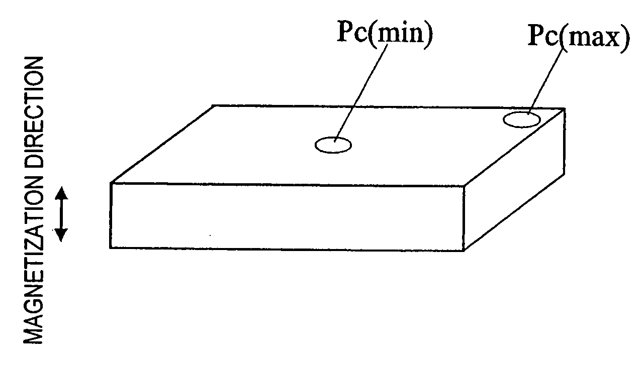
[0069] These magnets were magnetized such that their magnetization direction was parallel to their thickness direction. In this example, rare-earth magnets were used, and therefore, demagnetization was produced at a temperature higher than a normal temperature.

[0070] In comparing the values calculated by the magnetic field analysis method of the present invention with the actually meas...


PUM

PropertyMeasurementUnit
temperatureaaaaaaaaaa
operating temperatureaaaaaaaaaa

Abstract

A method and apparatus for magnetic field analysis, contributing to not only determining whether or not demagnetization would occur in a permanent magnet but also calculating its magnetic flux density distribution after the demagnetization, is provided. In a magnetic field analysis method according to the present invention, first, permeance coefficients at multiple sites in a permanent magnet and/or numerical values that are dependent on the permeance coefficients are calculated based on B-H curve data of the permanent magnet at a first temperature T1. Next, modified B-H curve data of the permanent magnet, which has been operated at a second temperature T2 that is different from the first temperature T1, are derived for the respective sites based on B-H curve data of the permanent magnet at the second temperature T2 and the permeance coefficients or the numerical values.

Description

BACKGROUND OF THE INVENTION [0001] 1. Field of the Invention [0002] The present invention relates to a method and apparatus for making a magnetic field analysis on a magnetic circuit including a permanent magnet of which the properties are subject to change due to demagnetization. The present invention also relates to a method for producing a permanent magnet by using such a method and apparatus for magnetic field analysis. [0003] 2. Description of the Related Art [0004] Recently, to design a magnetic circuit more efficiently and to further reduce its size, magnetic field analysis has sometimes been carried out using a computer simulation technique. Such magnetic field analysis may be performed by a method such as a finite element method in which permanent magnets with various shapes are evaluated by dividing them into a huge number of very small elements (or meshes). As those magnetic field analysis techniques have been developed, it has become possible to calculate the magnetic fl...

Claims


Application Information

Patent Timeline
Patent Type & Authority Applications(United States)
IPC IPC(8): G01R33/12G06F17/50
CPCG06F17/5018G06F30/23
Inventor NATSUMEDA, MITSUTOSHITAKABAYASHI, HIROFUMI
Owner SUMITOMO SPECIAL METAL CO LTD
Why Eureka
Try Eureka