Polarizer, polarization light source and image displayunit using them

a technology of polarizer and light source, applied in the field of polarizer components, can solve the problems of large number of parts, insufficient brightness enhancement system, and loss of optical properties,

Inactive Publication Date: 2005-07-14
NITTO DENKO CORP
View PDF33 Cites 45 Cited by
  • Summary
  • Abstract
  • Description
  • Claims
  • Application Information

AI Technical Summary

Benefits of technology

[0008] Therefore, it is an object of the present invention to provide a polarization component that can reflect obliquely-trans...

Problems solved by technology

However, since a large refractive index difference is required in principle when focusing by means of a prism sheet, the prism sheet must be disposed via an air layer or the like.
This may result in an optical loss caused by unnecessary reflection or scattering.
Another problem is that a large number of parts will be required.
For example, reflection and separation of circularly polarized light by a cholesteric liquid crystal is detailed in, for example, JP 03(1991)-45906 A, JP 06(1994)-324333 A, and JP 07(1995)-36032 A. However, such a brightness enhancement system cannot provide sufficient effects with respect to a light source whose focusing property is improved previously by using a prism sheet or the like, in comparison to a case where it is applied to a light source having a...

Method used


Image

  • Polarizer, polarization light source and image displayunit using them
  • Polarizer, polarization light source and image displayunit using them
  • Polarizer, polarization light source and image displayunit using them

Examples


first embodiment

(First Embodiment)

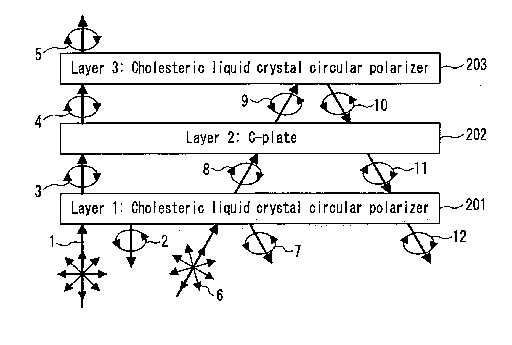
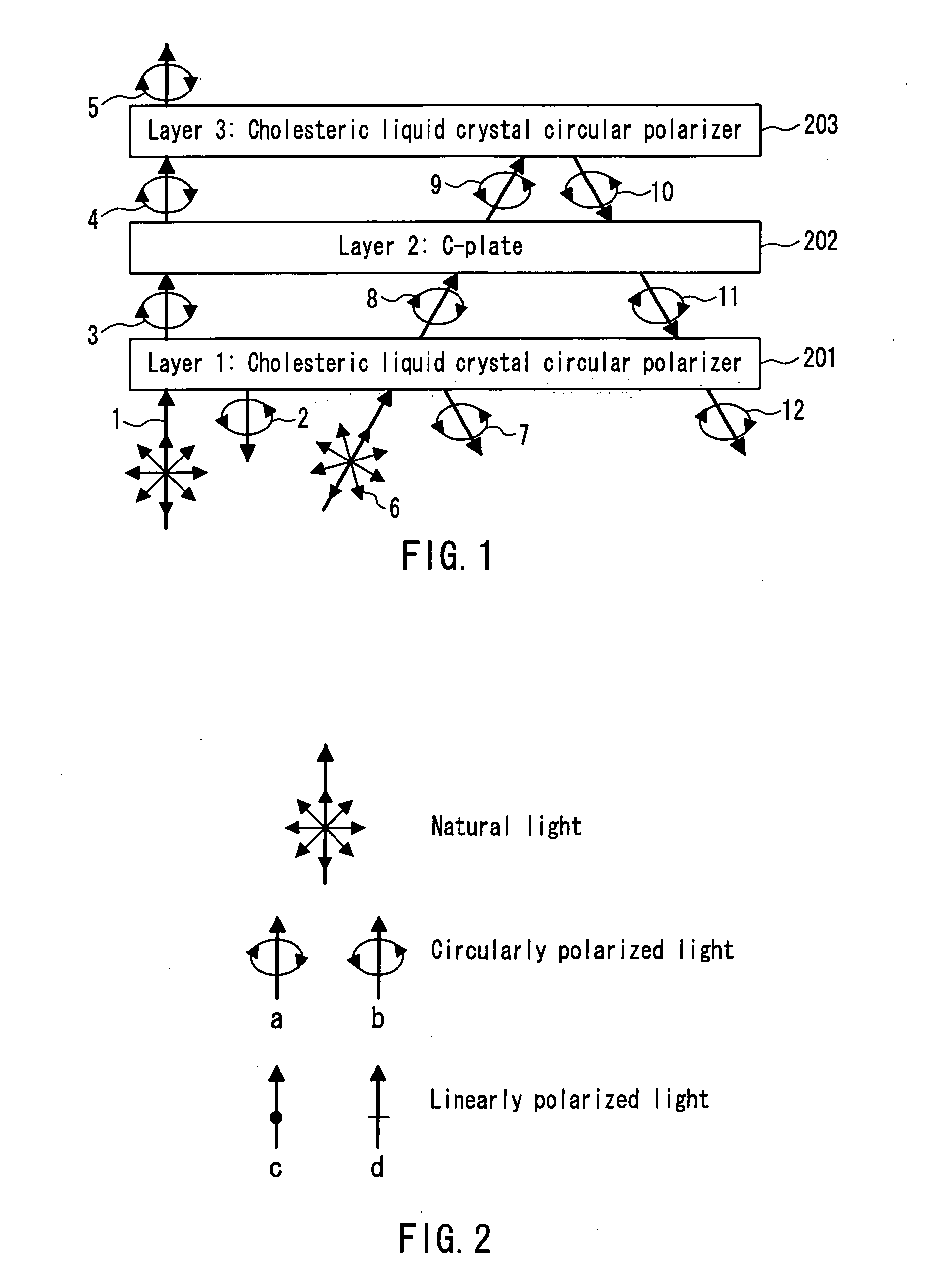
[0057] Referring to FIGS. 1 and 2, a mechanism of simultaneous expression of focusing and brightness enhancement in a polarization component of the present invention will be described below. However, the description below refers to only one embodiment of the present invention, and the present invention will not be limited by the description.

[0058]FIG. 1 shows this embodiment for a polarization component of the present invention. As shown in this figure, this polarization component is formed by laminating main elements of a cholesteric liquid crystal circular polarizer 201 (hereinafter, this may be referred to as ‘layer 1’), a C-plate 202 (hereinafter, this may be referred to as ‘layer 2’), and a cholesteric liquid crystal circular polarizer 203 (hereinafter, this may be referred to as ‘layer 3’) in this order, and light beams enter from the layer 1 side. In the embodiment shown in this figure, rotational directions of circularly polarized light beams passing throu...

second embodiment

(Second Embodiment)

[0085] Another embodiment of the present invention will be described below.

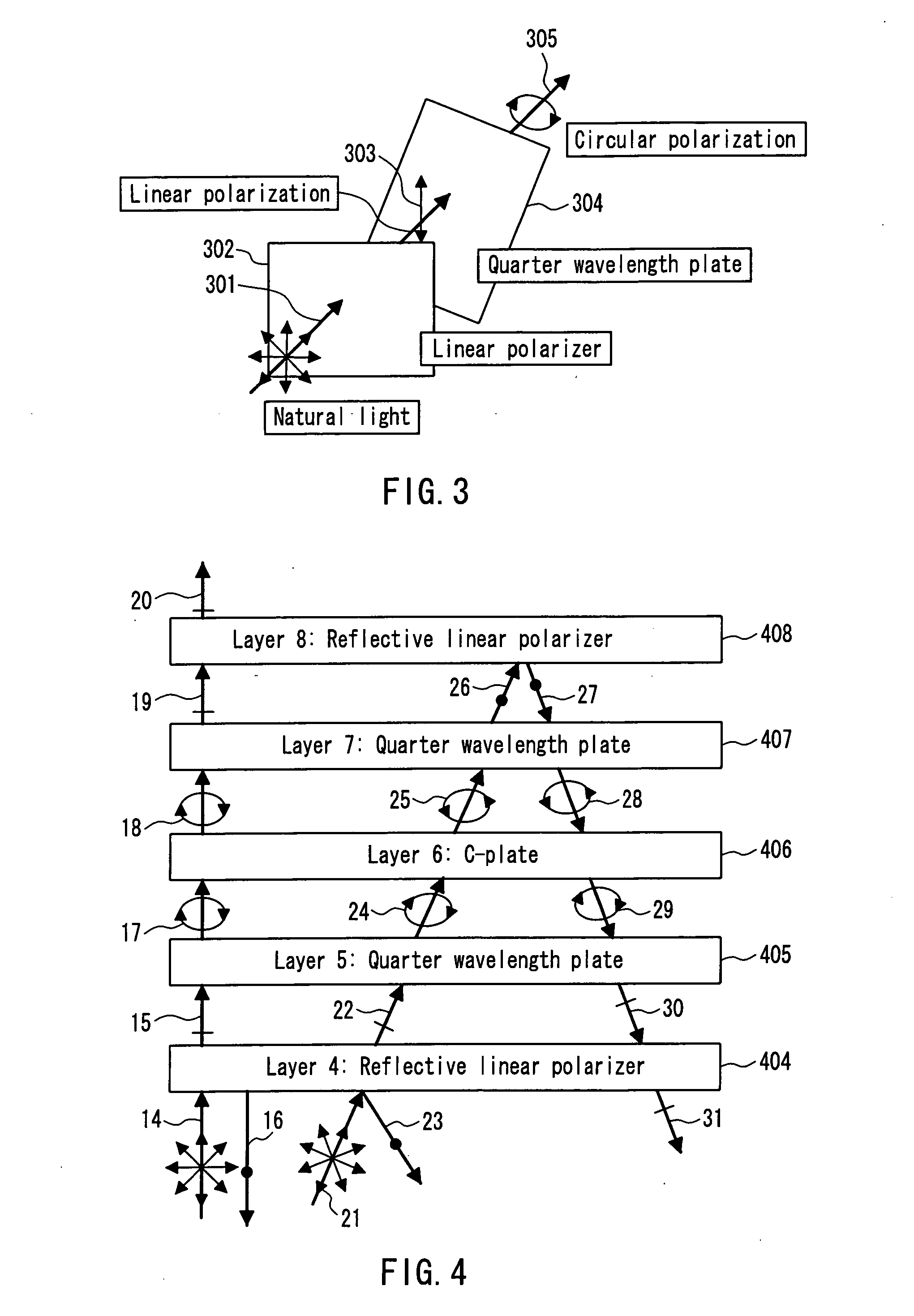
[0086] In the polarization component of the present invention, the reflective polarizer can be a reflective linear polarizer. More specifically, a polarization component of the present invention may include at least two reflective polarizer layers and an intermediate layer disposed between the reflective polarizer layers, the two reflective polarizer layers are reflective linear polarizer layers that selectively transmit one of linearly polarized light beams crossing each other at right angles while selectively reflecting the other,

[0087] the two reflective linear polarizer layers have selective reflection wavelength bands for selective reflection of polarized light, the bands overlapping each other at least partially,

[0088] the intermediate layer comprises a single optical layer or a laminate of at least two optical layers, and the intermediate layer has a function of transmitting an in...

third embodiment

(Third Embodiment)

[0124] Another embodiment of the present invention will be described below.

[0125] Similar effects can be obtained in this embodiment by laminating, at right angles or in parallel, two biaxial films whose front retardation (in-plane retardation) is λ / 4 and whose thickness direction retardation is at least λ / 2, instead of using a structure formed by sandwiching a C-plate with two quarter wavelength plate layers. In this case, a Nz coefficient (thickness direction retardation / in-plane retardation) of 2 or more can satisfy the requirement.

[0126] That is, a polarization component of the present invention may include at least two reflective linear polarizer layers and two quarter wavelength plate layers disposed between the reflective linear polarizer layers, wherein

[0127] the two reflective linear polarizer layers have selective reflection wavelength bands for selective reflection of polarized light, the selective reflection wavelength bands overlapping each other a...


PUM


Abstract

A polarization component, capable of efficiently reflecting an obliquely transmitted light beam toward a light source without degrading the transmission-polarization property of a perpendicular incident light beam, is provided. A C-plate having an oblique retardation of at least λ/8 with respect to a light beam inclined by at least 30° is disposed between at least two reflective circular polarizer layers whose selective reflection wavelength bands of polarized light overlapping each other. A combination of a reflective linear polarizer and a quarter wavelength plate may be used instead of the reflective circular polarizer. Alternatively, a combination of two reflective linear polarizer layers and two quarter wavelength plate layers (Nz≧2) disposed therebetween can provide a similar effect. Further, a combination of two reflective linear polarizer layers and a half wavelength plate (Nz≧1.5) disposed therebetween may be used.

Description

TECHNICAL FIELD [0001] The present invention relates to a polarization component. More specifically, the present invention relates to a polarization component that has excellent efficiency in use of diffuse light emitted from a light source, and that is used suitably for a high-brightness polarization light source and various image display apparatuses such as a highly-visible liquid crystal display apparatus, an organic EL display apparatus, PDP, and CRT. BACKGROUND ART [0002] For the purpose of improving visibility or the like of an image display apparatus, a technique of focusing light beams emitted from a light source toward a front direction so as to enhance the brightness has been used in general. More specifically, for example, a lens, a mirror (reflective layer) a prism or the like is used for utilizing refraction and reflection for focusing and parallelizing light beams, thereby enhancing the brightness. [0003] For example, in a liquid crystal display apparatus, a light beam...

Claims


Application Information

Patent Timeline
IPC IPC(8): G02B5/30G02F1/1335G02F1/13357G02F1/13363
CPCG02B5/3016G02B5/3025G02B5/3083H01L51/5281G02F1/13362G02F1/133634G02F2001/133543G02F1/133536G02F1/133543H10K59/8791G02B5/30G02F1/1335H10K50/86
Inventor HARA, KAZUTAKAMIYATAKE, MINORU
Owner NITTO DENKO CORP
Why Eureka
Try Eureka