Method and apparatus for a micro-actuator providing three-dimensional positioning to a slider in a hard disk drive

a micro-actuator and slider technology, applied in the direction of maintaining the head carrier alignment, recording information storage, instruments, etc., can solve the problems of reducing the reliability of the data stored on the disk, flying the read-write head and slider, and damage to the read-write head, so as to reduce the voltage requirements

Inactive Publication Date: 2005-07-14
SAMSUNG ELECTRONICS CO LTD
View PDF5 Cites 21 Cited by
  • Summary
  • Abstract
  • Description
  • Claims
  • Application Information

AI Technical Summary

Benefits of technology

[0017] It is preferred that the planar micro-actuator include two planar micro-actuator arms supporting the slider movement in the planar direction. It is also preferred that at least one of the micro-actuators include a piezoelectric device. The vertical micro-actuator preferably includes a bulk piezoelectric device. It may be preferred that the vertical micro-actuator be a multi-layer piezoelectric device to reduce the voltage requirements in stimulating the micro-actuator.

Problems solved by technology

There are problems with flying the read-write heads and sliders so near to the rotating disk surfaces.
Occasionally, the read-write heads can contact the disk surface, which tends to reduce the reliability of the data stored on the disk, and possibly damage the read-write head.
However, extending servo bandwidth is difficult, and has not significantly improved recently.
A problem arises when integrating micro-actuators into hard disk drives with multiple disk surfaces.
Changing many or most of the components of an actuator arm assembly, leads to increases in development expenses, retesting and recalibrating the production processes for reliability, and inherently increases the cost of production.
This has limited the use of micro-actuators to hard disk drives with only one active disk surface.

Method used


Image

  • Method and apparatus for a micro-actuator providing three-dimensional positioning to a slider in a hard disk drive
  • Method and apparatus for a micro-actuator providing three-dimensional positioning to a slider in a hard disk drive
  • Method and apparatus for a micro-actuator providing three-dimensional positioning to a slider in a hard disk drive

Examples


Embodiment Construction

[0036] The following description is provided to enable any person skilled in the art to make and use the invention and sets forth the best modes presently contemplated by the inventors for carrying out the invention. Various modifications, however, will remain readily apparent to those skilled in the art, since the generic principles of the present invention have been defined herein.

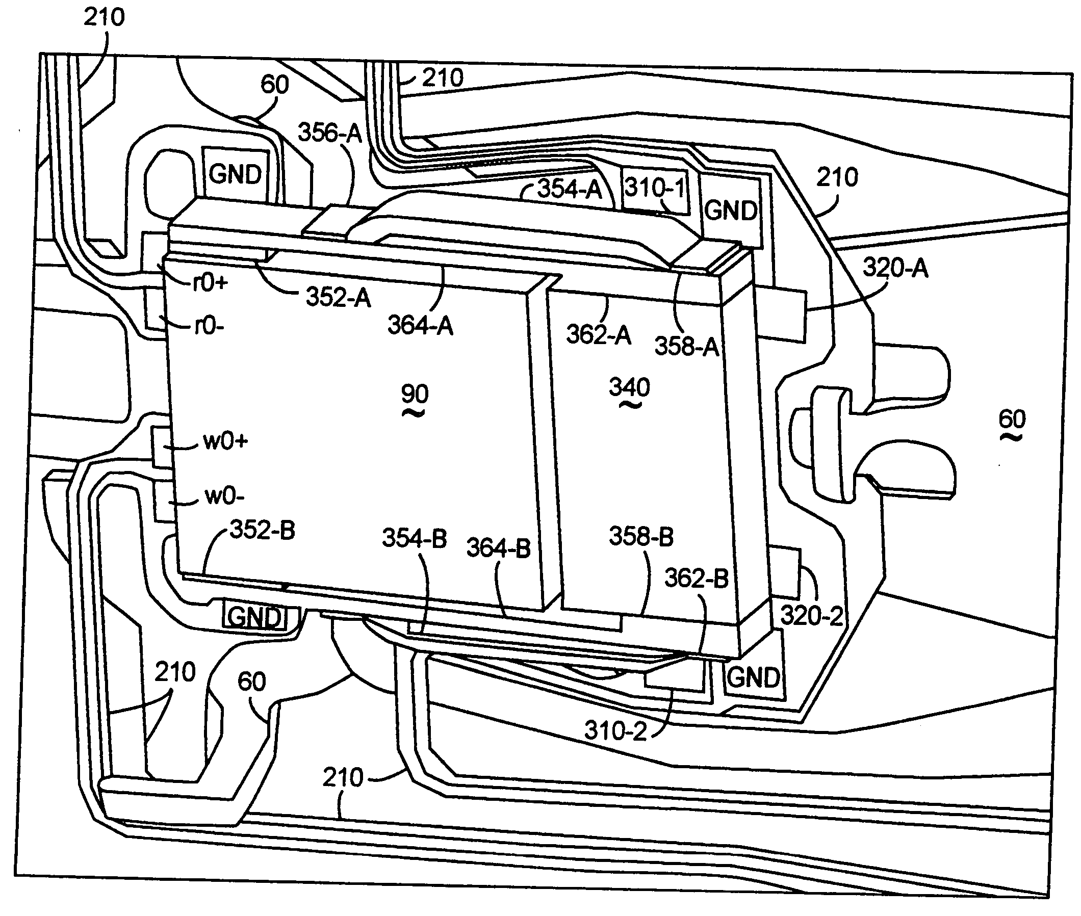
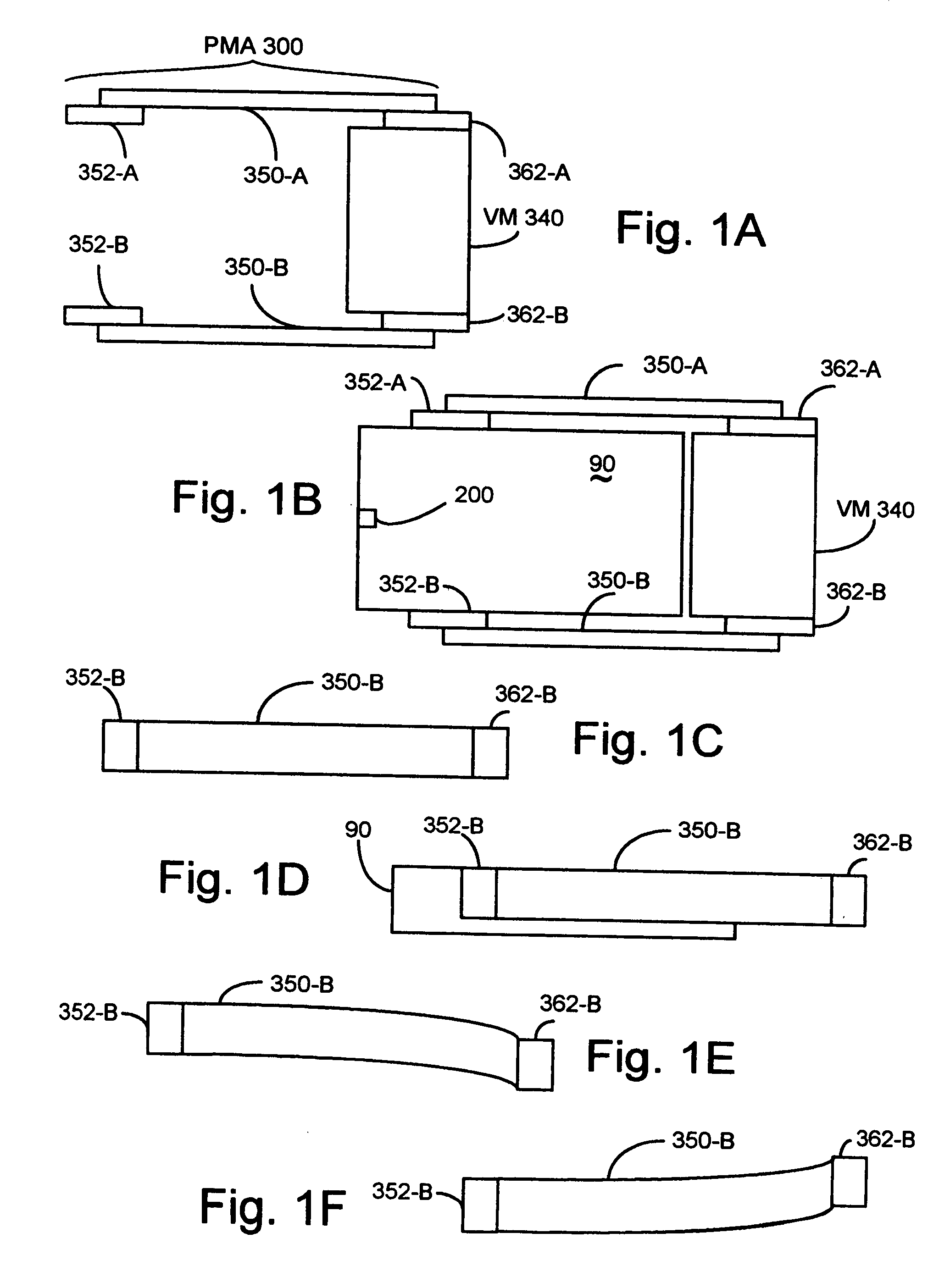
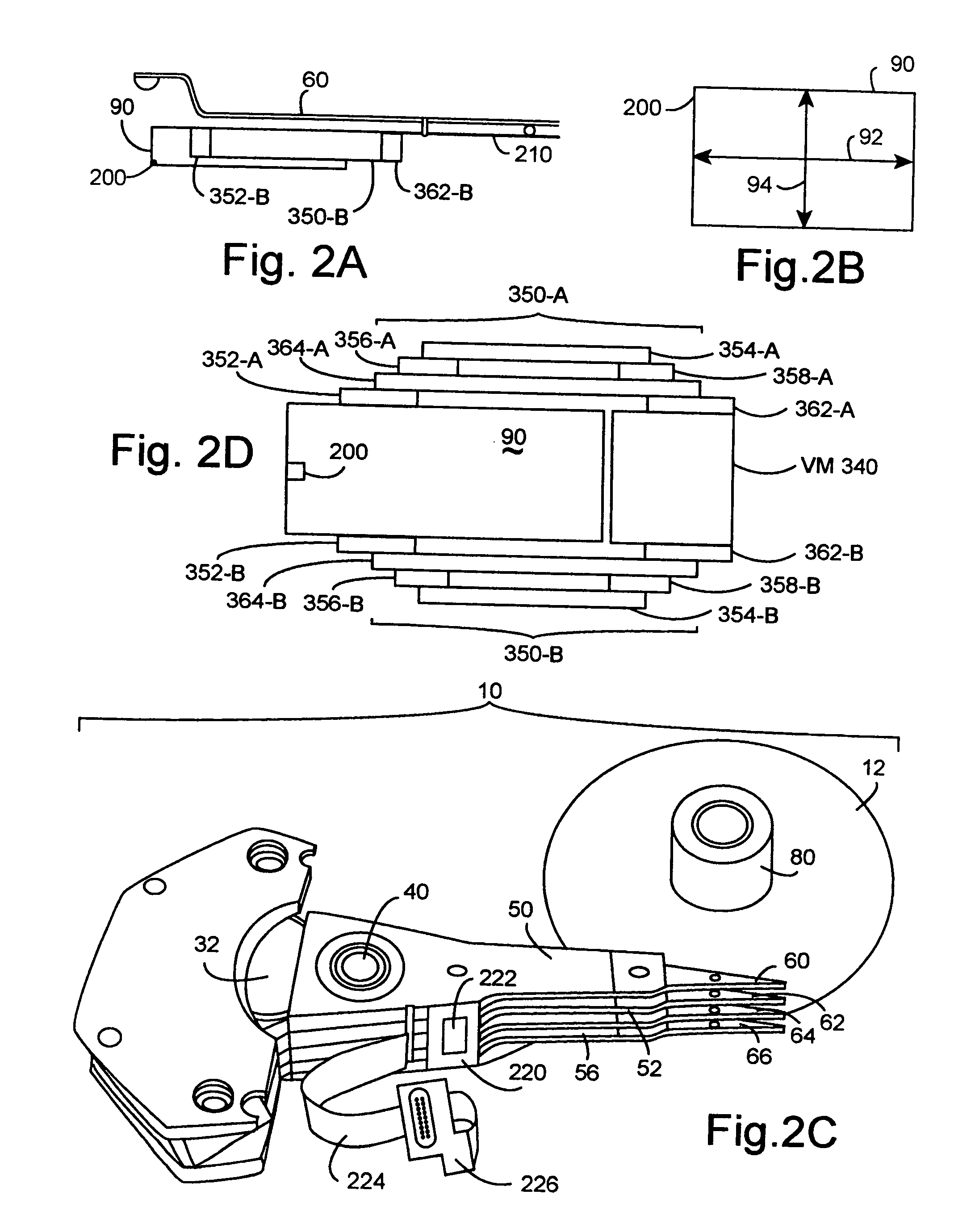
[0037] As shown in FIGS. 1A, 1B, 2D, and 7, the present invention includes a micro-actuator assembly comprising a planar micro-actuator 300, and a vertical micro-actuator 340. The planar micro-actuator 300 provides at least one planar micro-actuator arm 350-B for coupling 352-B to a slider 90, as shown in FIGS. 1B, 1D, 2A, and 7. The vertical micro-actuator 340 couples 362-B with the planar micro-actuator arm 350-B.

[0038] The planar micro-actuator 300 preferably includes two planar micro-actuator arms 350-A and 350-B, that supports movement of the slider 90 in the planar direction, as shown in FIGS. 1A...


PUM

PropertyMeasurementUnit
voltageaaaaaaaaaa
electrical stimulusaaaaaaaaaa
movementaaaaaaaaaa

Abstract

The present invention includes a micro-actuator assembly. The micro-actuator assembly includes a planar micro-actuator and a vertical micro-actuator. The planar micro-actuator provides at least one planar micro-actuator arm for coupling to a slider. The vertical micro-actuator couples with the planar micro-actuator arm. The planar micro-actuator arm supports moving the slider in a planar direction. The vertical micro-actuator supports moving the slider, through the micro-actuator arm, in a vertical direction. The planar micro-actuator may include two planar micro-actuator arms. It is preferred that at least one of the micro-actuators include a piezoelectric device. The vertical micro-actuator preferably includes a bulk piezoelectric device for cost reasons. The vertical micro-actuator may include a thermoelectric device supporting vertical slider movement. The invention includes manufacturing head gimbal assemblies, actuator arms, voice coil actuator assemblies, and hard disk drives. The hard disk drives, actuator assemblies, actuator arms, and head gimbal assemblies, are products of these processes.

Description

BACKGROUND OF THE INVENTION [0001] 1. Field of the Invention [0002] The present invention relates generally to micro-actuators positioning sliders in a hard disk drive and, more particularly, to a micro-actuator capable of three-dimensional positioning of a slider. [0003] 2. Background Information [0004] Modern hard disk drives may have one or more disks. Each disk may have two disk surfaces in use. The hard disk drives also include a servo controller that drives a voice coil actuator to position a read-write head near a track on the surface of a rotating disk. The read-write head communicates with the servo controller, providing feedback, which is used in controlling the read-write head's positioning near the track. The read-write head is embedded in a slider, which floats on a thin layer of air, known as an air bearing, a very short distance above the rotating disk surface. [0005] The trend in the hard disk drive industry is to increase the areal density of the rotating disk surfa...

Claims


Application Information

Patent Timeline
Patent Type & Authority Applications(United States)
IPC IPC(8): G11B21/02G11B5/48G11B5/55G11B5/56G11B5/596G11B7/085G11B21/21
CPCG11B5/4826G11B5/596G11B5/56G11B5/5552G11B7/085G11B21/02G11B21/21
Inventor KWON, HAESUNGSULLIVAN, MICHAELLEE, HYUNG JAI
Owner SAMSUNG ELECTRONICS CO LTD
Why Eureka
Try Eureka