
Apparatus for allowing handheld wireless devices to communicate voice and information over preexisting telephone lines

Inactive Publication Date: 2005-07-14
WIRELESS ROOTS
View PDF6 Cites 108 Cited by
  • Summary
  • Abstract
  • Description
  • Claims
  • Application Information

AI Technical Summary

Benefits of technology

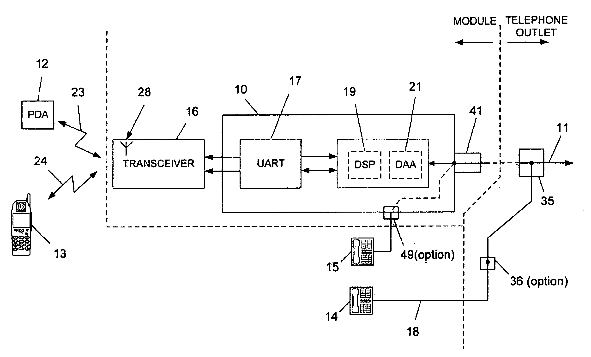
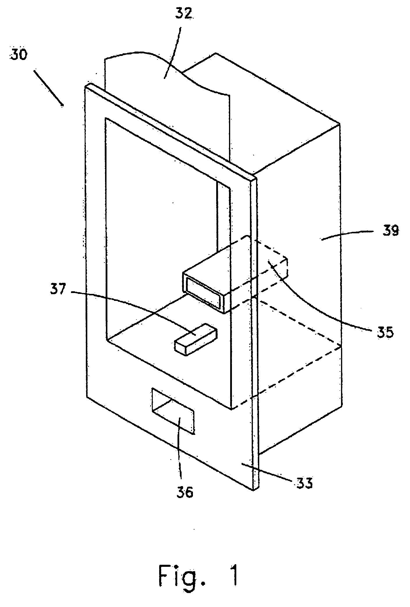
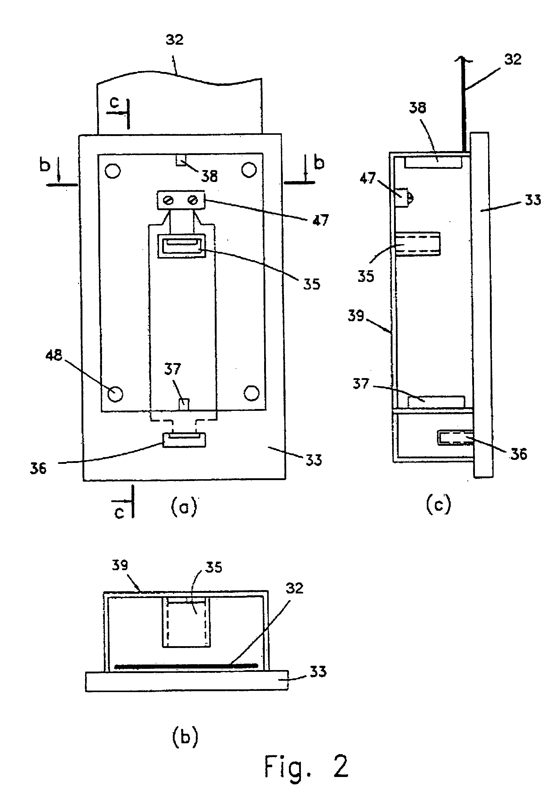
[0015] The telephone outlet is intended to be essentially completely mounted within a wall, replacing a preexisting conventional wall outlet related to telephone wiring systems, or added to telephone wiring systems, and the detachable module is designed to be essentially completely embedded within the telephone outlet, and electrically connected with its first wired end, via the telephone outlet, to a physical telephone line of the preexisting telephone wiring system. A standard wired link of the telephone outlet serves to intermediate between a wired telephone apparatus and the telephone line, thus duplicating and maintaining the original functionality of the conventional outlet that has been replaced by the telephone outlet.
[0021] The present invention utilizes standard electronic components, which are readily available on the market, as well as known communication protocols. However, the present invention is characterized by the electronic circuits and components being all encased in one, relatively small, detachable, removable apparatus, that may be easily plugged into, and easily disconnected from a connecting means, normally a conventional jack such as RJ11, by mating to the latter connecting means a corresponding plug that is externally affixed to a corresponding side wall of the detachable module, and provides the required electrical connectivity between the electronic circuits and components, encased by the detachable module, to the corresponding physical telephone line.
[0026] According to an aspect of the present invention, the detachable module and telephone outlet may replace a conventional base-station of a conventional cordless telephone system, and a corresponding, e.g., Bluetooth-enabled apparatus (e.g., a PDA) may replace the handset of the conventional base-station of the conventional cordless telephone system. The module and Bluetooth-enabled apparatus may, in fact, be considered as a new type of cordless telephone system, which is advantageous over the conventional cordless telephone system, since the new type of cordless telephone system does not require any cables nor an external power system for operation, and the new type of cordless telephone system could be very easily and conveniently moved from one location to another. In addition, the space, which is normally consumed by base-stations of conventional cordless telephone systems, could be spared that way.

Problems solved by technology

Consumers are increasingly unwilling to accept less than full communication services and convenience while away from homes and offices.
But while communications systems are providing more services, they are simultaneously becoming more complex.
While conventional solutions employ combinations of wired and wireless segments in a single network, they do not fully satisfy the necessary requirements of simplicity, efficiency and portability.
For example, the kit disclosed in WO 01 / 80543 A2 is intended to be permanently attached to a wall, which is undesirable for structural, functional and economic reasons, since such a module could not be conveniently removed and used somewhere else.
While this kit makes it possible to attach a data oriented device to an external communication system through existing lines, the user is still restricted to a limited number of fixed locations.
In other words, the module and outlet that encase it do not provide a more universal solution, according to which there should be provided a detachable and portable module that could be easily coupled to, and removed from, a conventional jack, such as RJ11, that is connected to a telephone line.

Method used


Image

  • Apparatus for allowing handheld wireless devices to communicate voice and information over preexisting telephone lines
  • Apparatus for allowing handheld wireless devices to communicate voice and information over preexisting telephone lines
  • Apparatus for allowing handheld wireless devices to communicate voice and information over preexisting telephone lines

Examples


Embodiment Construction

[0040] FIGS. 1 to 5 structurally illustrate the apparatus according to the most preferred embodiment of the invention. The housing part of the apparatus (i.e., the telephone outlet) is intended to be installed in a wall of a room in which voice / data generating / receiving apparatuses are to be used. The apparatus comprises a telephone outlet 30 (FIG. 1) and a detachable module 31 (FIG. 3), which are coupled as will be described. Embodiments of coupling / decoupling mechanisms, for coupling / decoupling the module to / from the telephone outlet, are schematically illustrated in FIG. 7a and FIG. 7b. However, as explained, operation of the module (31) does not require any housing at all, as it could be simply coupled to a conventional (telephone) jack of, e.g., a conventional wall telephone outlet. The telephone outlet serves as a convenient and aesthetic “docking station” for the module in locations frequently used.

[0041] Telephone outlet 30 is seen in perspective view in FIG. 1, in front vi...


PUM


Abstract

Communication apparatus for interfacing between wired and wireless voice / data generating / receiving apparatuses and a physical telephone line of a communication network that comprises a telephone outlet, which is mounted within a wall of a building and includes first and second connecting means. These connecting means are electrically connected to each other and to the physical telephone line. The second connecting means allow connecting a wired telephone apparatus to the telephone line. A detachable module is designed to be completely embedded within the telephone outlet, whenever inserted into the outlet, mechanically fits into, and electrically adapted to cooperate with the outlet. The module has a wireless end and first and second wired ends, and provides wireless coupling between the voice / data generating / receiving apparatus and the telephone line by utilizing the wireless end and wired coupling between the module to the telephone line, which is obtained by utilizing the first wired end and the first connection means. The module comprises all the circuit components required for receiving and transmitting the wireless voice / digital information and, if required, to transform the format of the received voice / digital information into a format complying with a communication protocol suitable to be fed to the communication network. The first wired end of the module comprises electrical contacts for providing the circuit components power, which exists on the telephone line, and signal connectivity, and is capable of mating with the first connection means. The second wired end of the module is designed to be completely embedded within the module, and intermediates between a wired telephone apparatus and the telephone line.

Description

FIELD OF THE INVENTION [0001] This invention relates to a communication apparatus, for transmitting to and receiving from a handheld device, wireless voice and data, whether digital or analog, over a telecommunication network, in particular a preexisting one such as a conventional telephone wiring system. BACKGROUND OF THE INVENTION [0002] As communications technologies become more complex, there is a growing need for telephone communication to be more tightly coupled with data oriented devices, such as Personal Computers (PCs) and Personal Organizers or Personal Digital Assistants (PDAs). The PCs and PDAs contain phone address listings, scheduling information and personal databases that are essential for effective and enhanced communication. [0003] Consumers are increasingly unwilling to accept less than full communication services and convenience while away from homes and offices. But while communications systems are providing more services, they are simultaneously becoming more c...

Claims


Application Information

Patent Timeline
IPC IPC(8): H04M1/725
CPCH04M2250/02H04M1/725
Inventor WURTZEL, LEONARDEHRLICH, EDWARDMANDELZWEIG, DAVID
Owner WIRELESS ROOTS
Learn More