Method and apparatus for compactly coupling an optical fiber and a planar optical waveguide

Active Publication Date: 2005-07-14
LUCENT TECH INC
View PDF5 Cites 14 Cited by
  • Summary
  • Abstract
  • Description
  • Claims
  • Application Information

AI Technical Summary

Benefits of technology

[0010] In accordance with the invention, an optical fiber is coupled to a planar waveguide through 1) a series of planar waveguide segments of enlarged cross section and 2) a segment o

Problems solved by technology

Unfortunately there is a problem in coupling light from the transmission fiber into a planar waveguide.
In addition to a mismatch in refractive indices, there is also a mismatch in core size.
The core size for a typical optical fiber is significantly larger than the optimal core size for a single mode planar waveguide; therefore, their optical modes don't match because the field is more confined in the waveguide than in the fiber.
As a consequence of these mismatches, direct coupling of a fiber to the planar waveguide would incur p

Method used


Image

  • Method and apparatus for compactly coupling an optical fiber and a planar optical waveguide
  • Method and apparatus for compactly coupling an optical fiber and a planar optical waveguide
  • Method and apparatus for compactly coupling an optical fiber and a planar optical waveguide

Examples


example 1

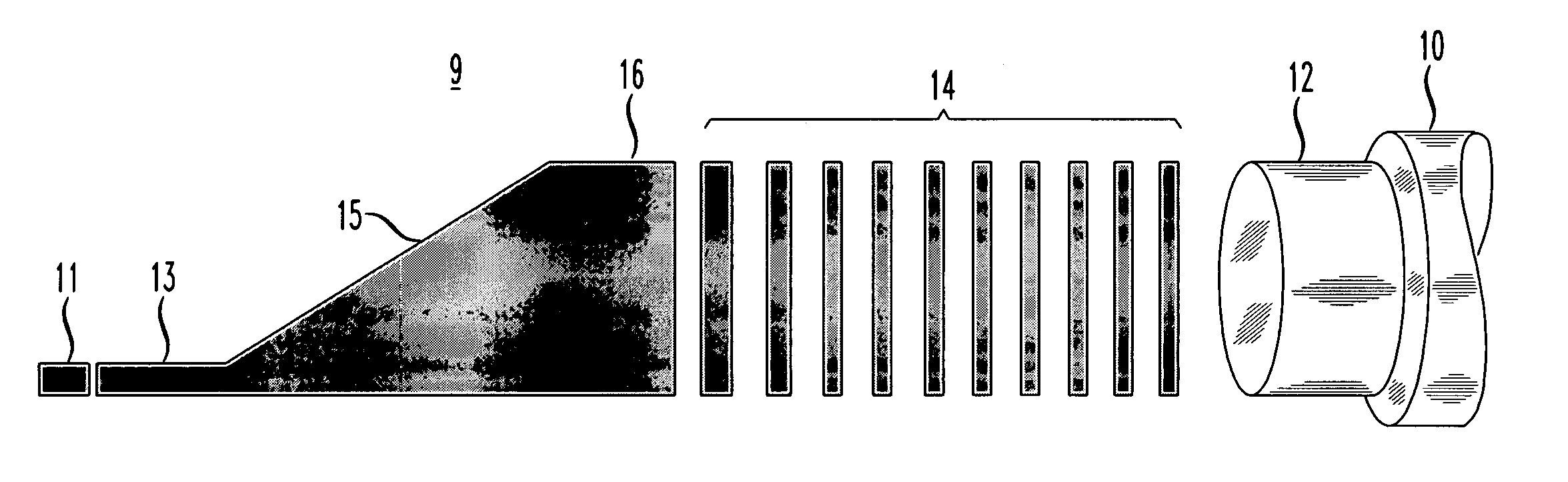
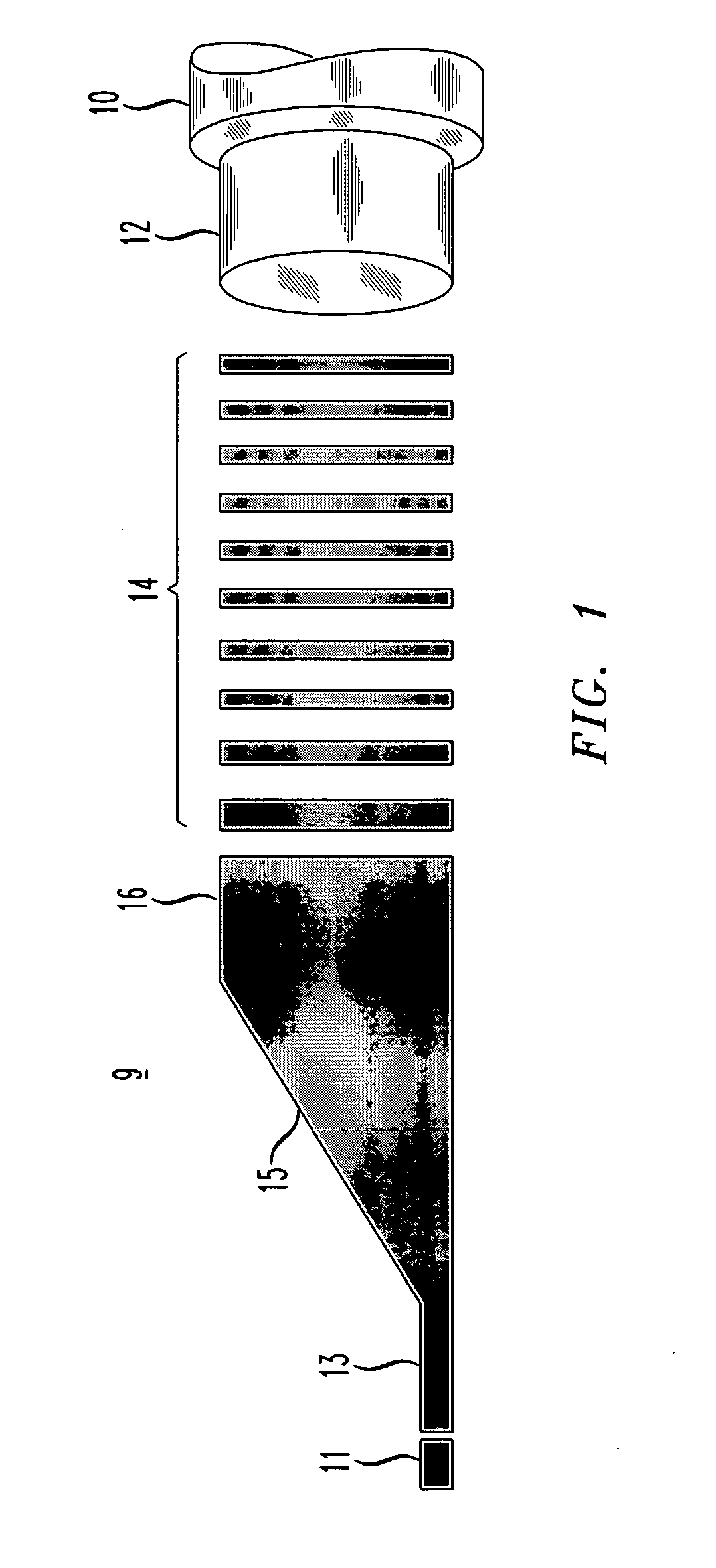
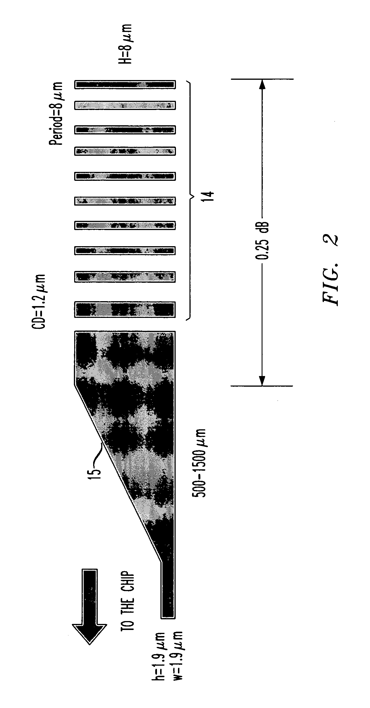
[0028]FIG. 2 schematically illustrates an arrangement for coupling an optical fiber having an 8 micrometer core with a high 6% delta planar waveguide of dimension 1.9×1.9 micrometers. The segmented section 14 comprises 10 high delta segments coupling from the fiber core to a tapered section 15. Each segment has a cross section of 8×8 micrometers and successive segments are periodically spaced 8 micrometers apart (center-to-center). Successive segments have increasing thickness in the longitudinal direction from the fiber to the tapered section so that light from the fiber experiences an increasing effective index as it approaches the continuous high delta tapered section. The tapered section includes a 110 micrometer length without taper and a 250 micrometer length without taper and a 250 micrometer region of linear taper down to planar waveguide dimension. The coupling loss is about 0.25 dB from input segment to the beginning of the linear taper. The loss in the adiabatic taper dep...

example 2

[0029] For coupling an optical fiber to 4% delta planar waveguide, a similar arrangement shown in FIG. 3 can have 7×7 micrometer segments periodically spaced by 9 micrometers. Total coupling loss is about 0.18 dB.

example 3

[0030]FIG. 4 schematically illustrates an arrangement using a tapered section 15 that is step tapered rather than continuously tapered. It uses ten 7×7 micrometer segments to couple from a fiber (not shown) to a step tapered section 15. The section 15 is tapered downward 0.43 micrometers in each of ten 25 micrometer steps. The total coupling loss is about 0.35 dB for coupling to a 4% delta planar waveguide.

[0031] It can now be seen that the invention includes a device for optically coupling an optical fiber to a planar waveguide. The device comprises a waveguiding structure comprising a segmented guiding position and a tapered guiding portion, both guiding portions disposed in a lower refractive index cladding region between the fiber and the planar waveguide.

[0032] The segmented guiding portion comprises a series of spaced apart segments of higher refractive index material. The segments have longitudinal cross sections substantially equal to the cross section of the fiber core, a...


PUM


Abstract

In accordance with the invention, an optical fiber is coupled to a planar waveguide through 1) a series of planar waveguide segments of enlarged cross section and 2) a segment of vertically tapered cross section. The combination of spaced segments and tapered segments provide efficient coupling over a much shorter length than required for conventional adiabatic coupling.

Description

FIELD OF THE INVENTION [0001] This invention relates to a method and apparatus for compactly and efficiently coupling light from an optical fiber into a planar waveguide and vice versa. BACKGROUND OF THE INVENTION [0002] Planar waveguide devices are important components of optical fiber communication systems. Such systems typically comprise long lengths of fiber for transmission and often use planar waveguide devices to perform a variety of processes such as filtering, multiplexing signal channels, demultiplexing, compensating chromatic dispersion and compensating polarization dispersion. [0003] An optical fiber is typically in the form of a thin strand of glass having a central core of circular cross section peripherally surrounded by concentric cladding glass. The core has a higher refractive index than the cladding so that the light is retained in the core by total internal reflection and propagates in a fiber mode. For long distance transmission the core dimensions are typically...

Claims


Application Information

Patent Timeline
IPC IPC(8): G02B6/26G02B6/12G02B6/122G02B6/132G02B6/136G02B6/14G02B6/30G02B27/00
CPCG02B6/1228G02B6/132G02B2006/12173G02B6/305G02B6/136G02B6/26G02B27/00
Inventor MADSEN, CHRISTI KAYRASRAS, MAHMOUD
Owner LUCENT TECH INC
Why Eureka
Try Eureka