Optical fiber and manufacturing method thereof and image forming apparatus

a manufacturing method and optical fiber technology, applied in the field of optical fiber and manufacturing method thereof, can solve the problems of troublesome replacement of a new semiconductor laser, low reproducibility of rectangular core b>62/b>, difficult cooling, etc., and achieve low cost, good image quality, and small variations in line width and dot density (coverage) caused by increasing or decreasing light quantity.

Inactive Publication Date: 2005-07-14
FUJIFILM HLDG CORP +1
View PDF7 Cites 13 Cited by
  • Summary
  • Abstract
  • Description
  • Claims
  • Application Information

AI Technical Summary

Benefits of technology

[0024] According to the fourth aspect, the recording medium is exposed by focusing the light beam output from the optical fiber of the first aspect with the optical focusing system. Since a profile of the light beam output from the optical fiber has a rectangular shape, a shape of the light beam spot focused on the recording medium also becomes rectangular. Therefore, variations in line width and dot density (coverage...

Problems solved by technology

However, since a broad area type semiconductor laser has a high output, the amount of heat generated is large and, particularly when arrayed, there is a problem that cooling becomes difficult.
Further, when a broad area type semiconductor laser is incorporated as a light beam output source into an exposure head of an image forming apparatus, there is the problem that replacement of a new semiconductor laser becomes troublesome when a semiconductor laser stops functioning correctly.
That is, reproducibility of the rectangular core 62 is not good.
That is, since the interface betwee...

Method used


Image

  • Optical fiber and manufacturing method thereof and image forming apparatus
  • Optical fiber and manufacturing method thereof and image forming apparatus
  • Optical fiber and manufacturing method thereof and image forming apparatus

Examples


Embodiment Construction

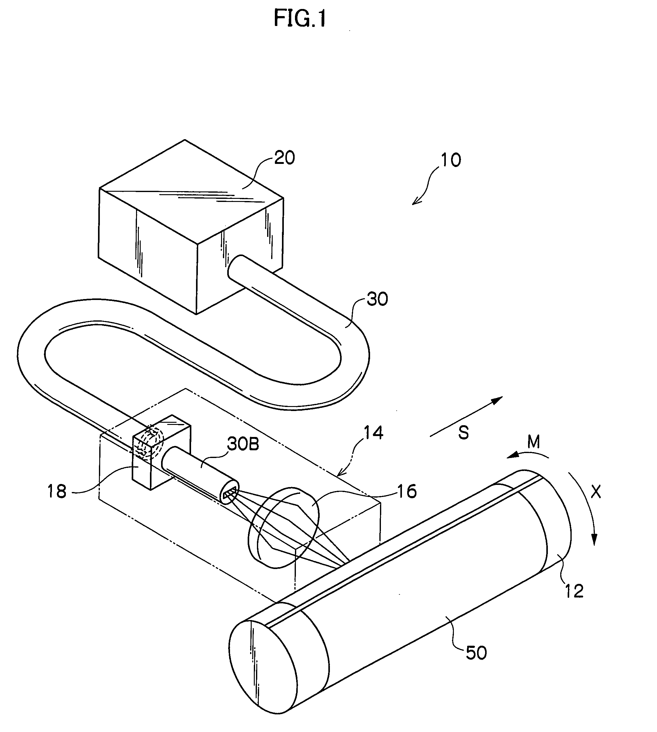
[0034] Referring to the accompanying drawings, an embodiment of the present invention will be described in detail below. FIG. 1 shows an example of an image forming apparatus 10 according to the invention. A heat mode type photosensitive material 50 which is of the recording medium is mounted on (absorbed onto) an outer peripheral surface of a cylindrical drum 12 which rotates at a constant speed. The heat mode type photosensitive material 50 is a photosensitive material using an evaporation film ablation method. Since the image is directly written on the heat mode type photosensitive material 50 by a laser or the like, heat mode type photosensitive materials are of interest for digital plate making systems. The heat mode type photosensitive material 50 is not limited to a photosensitive material using an evaporation film ablation method. Photosensitive materials utilizing thermal induced changes, such as phase transition and insolubilization, can also be used.

[0035] An exposure he...


PUM

PropertyMeasurementUnit
Diameteraaaaaaaaaa
Sizeaaaaaaaaaa
Widthaaaaaaaaaa

Abstract

The present invention provides an optical fiber having a rectangular core in which propagation loss of a light beam is small and manufacturing can be performed at low cost, a method of manufacturing the optical fiber, and an image forming apparatus including the optical fiber. The optical fiber having the core, whose sectional shape in a direction orthogonal to an optical axis direction of a light beam becomes rectangular, is formed by: filling a cylindrical tube with multiple hollow capillaries; extracting hollow capillaries located in a rectangular area having a predetermined size in a portion which is substantially central to the tube; inserting rods having the same diameter as the extracted hollow capillaries to replace the hollow capillaries to produce a preform; performing wire drawing while the preform is melt-fused; and covering the preform with a cover layer.

Description

CROSS-REFERENCE TO RELATED APPLICATION [0001] This application claims priority under 35 USC 119 from Japanese Patent Application No. 2004-4096, the disclosure of which is incorporated by reference herein. BACKGROUND OF THE INVENTION [0002] 1. Field of the Invention [0003] The present invention relates to: an optical fiber, which guides a light beam; a method of manufacturing the optical fiber; and an image forming apparatus, which forms an image by irradiating a recording medium with the light beam guided by the optical fiber. [0004] 2. Description of the Related Art [0005] An image forming apparatus is know in which: an optical fiber is connected to a light source, such as a semiconductor laser; a light beam output from the optical fiber is focused with a focusing lens (focusing optical system); and a recording medium, arranged at the focusing position of the light beam, is irradiated to form (record) an image on a recording medium. [0006] An optical fiber having a core / cladding co...

Claims


Application Information

Patent Timeline
IPC IPC(8): G02B6/02C03B37/012G02B6/00G02B6/032G02B6/42
CPCC03B37/01211C03B2203/12C03B2203/14G02B2006/0098G02B6/02338G02B6/02347G02B6/4206G02B6/02333
Inventor SUNAGAWA, HIROSHI
Owner FUJIFILM HLDG CORP
Why Eureka
Try Eureka