Electro-kinetic air transporter and conditioner devices with 3/2 configuration having driver electrodes

a technology of electric motor and driver electrode, which is applied in the direction of lighting and heating apparatus, domestic cooling apparatus, pulse technique, etc., can solve the problems of insufficient quantity, achieve the effect of increasing the particle collection efficiency, increasing the rate and/or volume of airflow, and reducing arcing

Inactive Publication Date: 2005-07-14
SHARPER IMAGE ACQUISITION
View PDF98 Cites 21 Cited by
  • Summary
  • Abstract
  • Description
  • Claims
  • Application Information

AI Technical Summary

Benefits of technology

[0010] The insulation (i.e., dielectric material) on the driver electrodes allows the voltage potential to be increased between the driver and collector electrodes, to a voltage potential that would otherwise cause arcing if the insulation were not present. This increased voltage potential increases particle collection efficiency. Additionally, the insulation will reduce, and likely prevent, any arcing from occurring if a carbon path is formed between the collector and driver electrodes, e.g., due to an insect getting caught therebetween.
[0016] The embodiments as describe above have some or all of the advantages of increasing the particle collection efficiency, increasing the rate and / or volume of airflow, reducing arcing, and / or reducing the amount of ozone generated. Further, ions generated using many of the embodiments of the present invention will be more of the negative variety as opposed to the positive variety.

Problems solved by technology

Further, the corona discharge produced between the electrode arrays can release ozone into the ambient environment, which can eliminate odors that are entrained in the airflow, but is generally undesirable in excess quantities.

Method used


Image

  • Electro-kinetic air transporter and conditioner devices with 3/2 configuration having driver electrodes
  • Electro-kinetic air transporter and conditioner devices with 3/2 configuration having driver electrodes
  • Electro-kinetic air transporter and conditioner devices with 3/2 configuration having driver electrodes

Examples


Embodiment Construction

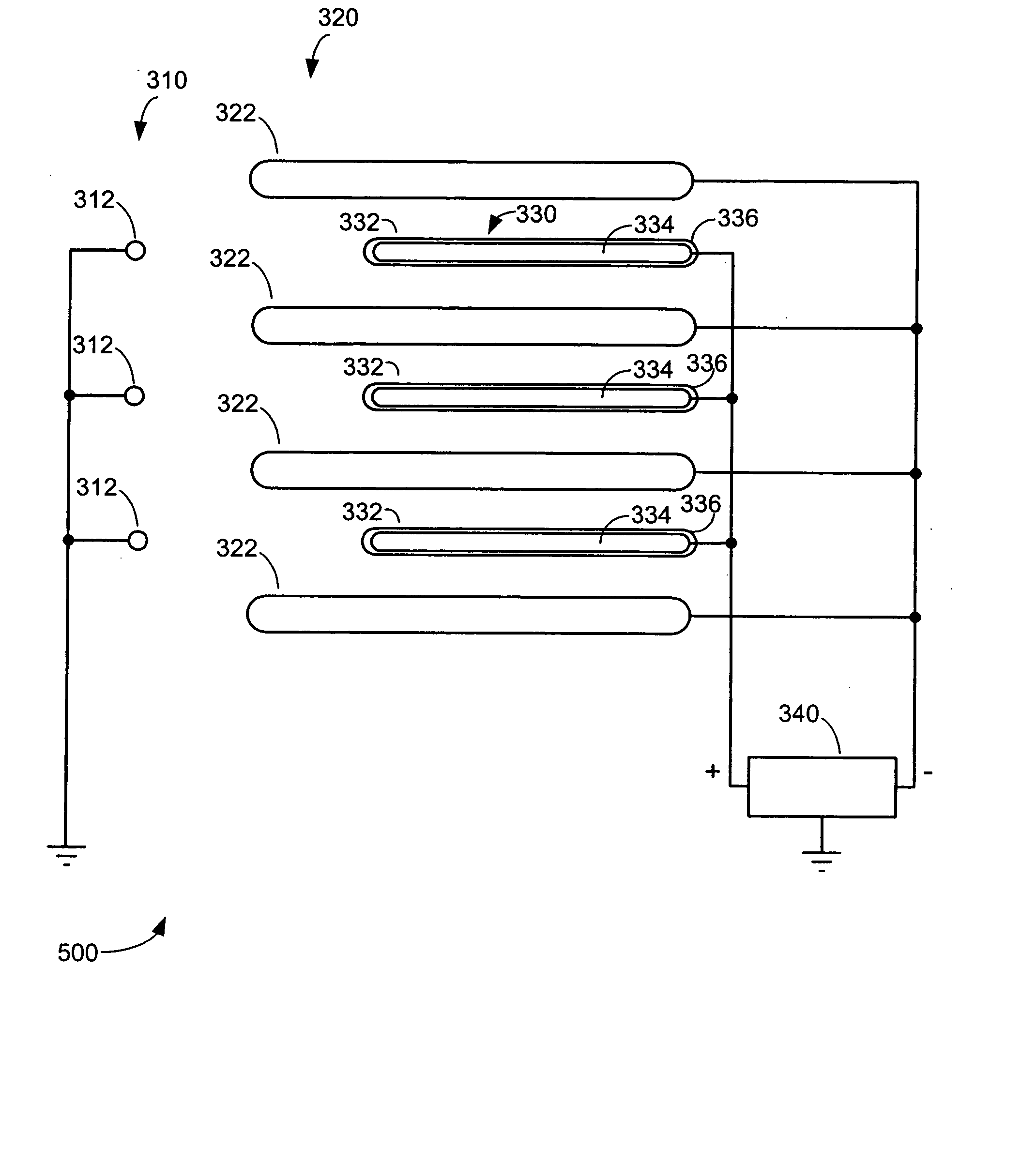
[0035]FIG. 3 illustrates schematically, an electro-kinetic conditioner system 300 according to an embodiment of the present invention. The system includes a first array 310 (i.e., emitter array) of emitter electrodes 312, a second array 320 (i.e. collector array) of collector electrodes 322 and a third array 330 of insulated driver electrodes 330. In this embodiment, the first array 310 is shown as being connected to a positive terminal of a high voltage source 340, and the second array 320 is shown as being connected to a negative terminal of the high voltage source 340. The third array 330 of insulated driver electrodes 332 are shown as being grounded.

[0036] Each insulated driver electrode 332 includes an electrically conductive electrode 334 that is covered by a dielectric material 336. In accordance with an embodiment of the present invention, the dielectric material 336 is heat shrink tubing. During manufacture, the heat shrink tubing is placed over the driver electrodes 334 a...


PUM


Abstract

Electro-kinetic air transporter and conditioner systems and methods are provided. A system includes at least one emitter electrode and at least a one collector (and likely, at least a pair of collector electrodes) that are downstream from the emitter electrode. An insulated driver electrode is located adjacent a collector electrode, and where there is at least a pair of collector electrodes, between each pair of collector electrodes. A high voltage source provides a voltage potential to the at least one of the emitter electrode and the collector electrode(s), to thereby provide a potential different therebetween. The insulated driver electrode(s) may or may not be at a same voltage potential as the emitter electrode, but should be at a different voltage potential than the collector electrode(s).

Description

PRIORITY CLAIM [0001] The present application is a continuation of co-pending application entitled “ELECTRO-KINETIC AIR TRANSPORTER-CONDITIONER DEVICES WITH INSULATED DRIVER ELECTRODES” application Ser. No. 10 / 717,420, filed Nov. 19, 2003 (Attorney Docket No. SHPR-01414US1) which claims priority under 35 U.S.C. 119(e) to U.S. Provisional Patent Application No. 60 / 500,437, filed Sep. 5, 2003, entitled “ELECTRO-KINETIC AIR TRANSPORTER-CONDITIONER DEVICES WITH INSULATED DRIVER ELECTRODES” (Attorney Docket No. SHPR-0 1414US0), both of which are hereby incorporated herein by reference. CROSS-REFERENCE TO RELATED ART [0002] The present invention is related to the following patent applications and patent, each of which is incorporated herein by reference: U.S. patent application Ser. No. 10 / 074,207, filed Feb. 12, 2002, entitled “Electro-Kinetic Air Transporter-Conditioner Devices with Interstitial Electrode”; U.S. patent application Ser. No. 10 / 074,827, filed Feb. 12, 2002, “Electro-Kinet...

Claims


Application Information

Patent Timeline
Patent Type & Authority Applications(United States)
IPC IPC(8): B03C3/08B03C3/47
CPCB03C3/08B03C2201/14B03C3/47
Inventor BOTVINNIK, IGOR Y.PARKER, ANDREW J.TAYLOR, CHARLES E.
Owner SHARPER IMAGE ACQUISITION
Why Eureka
Try Eureka