Component of a fuel cell unit

a fuel cell unit and component technology, applied in the direction of fuel cell details, solid-state devices, surface reaction electrolytic coating, etc., can solve the problem of not being able to achieve a satisfactory insulation effect, the electric resistance at the operating temperature of a high-temperature fuel cell unit,

Inactive Publication Date: 2005-07-14
ELRINGKLINGER AG
View PDF8 Cites 13 Cited by
  • Summary
  • Abstract
  • Description
  • Claims
  • Application Information

AI Technical Summary

Benefits of technology

[0047] Claims 33 to 40 are directed to a method of manufacturing a fuel cell stack, which comprises a plurality of fuel cell units, whereby at least one component that has an electric insulation effect at the operating temperature of the fuel cell stack is manufactured by the method according to the invention and a plurality of fuel cell units are stacked one on top of the other along a stacking direction.

Problems solved by technology

In the case of some of the sealing materials normally used, the electrical resistance at the operating temperature of a high-temperature fuel cell unit (in the range of approximately 800° C. to approximately 900° C.) is no longer high enough to achieve a satisfactory insulation effect.

Method used


Image

  • Component of a fuel cell unit
  • Component of a fuel cell unit
  • Component of a fuel cell unit

Examples


Embodiment Construction

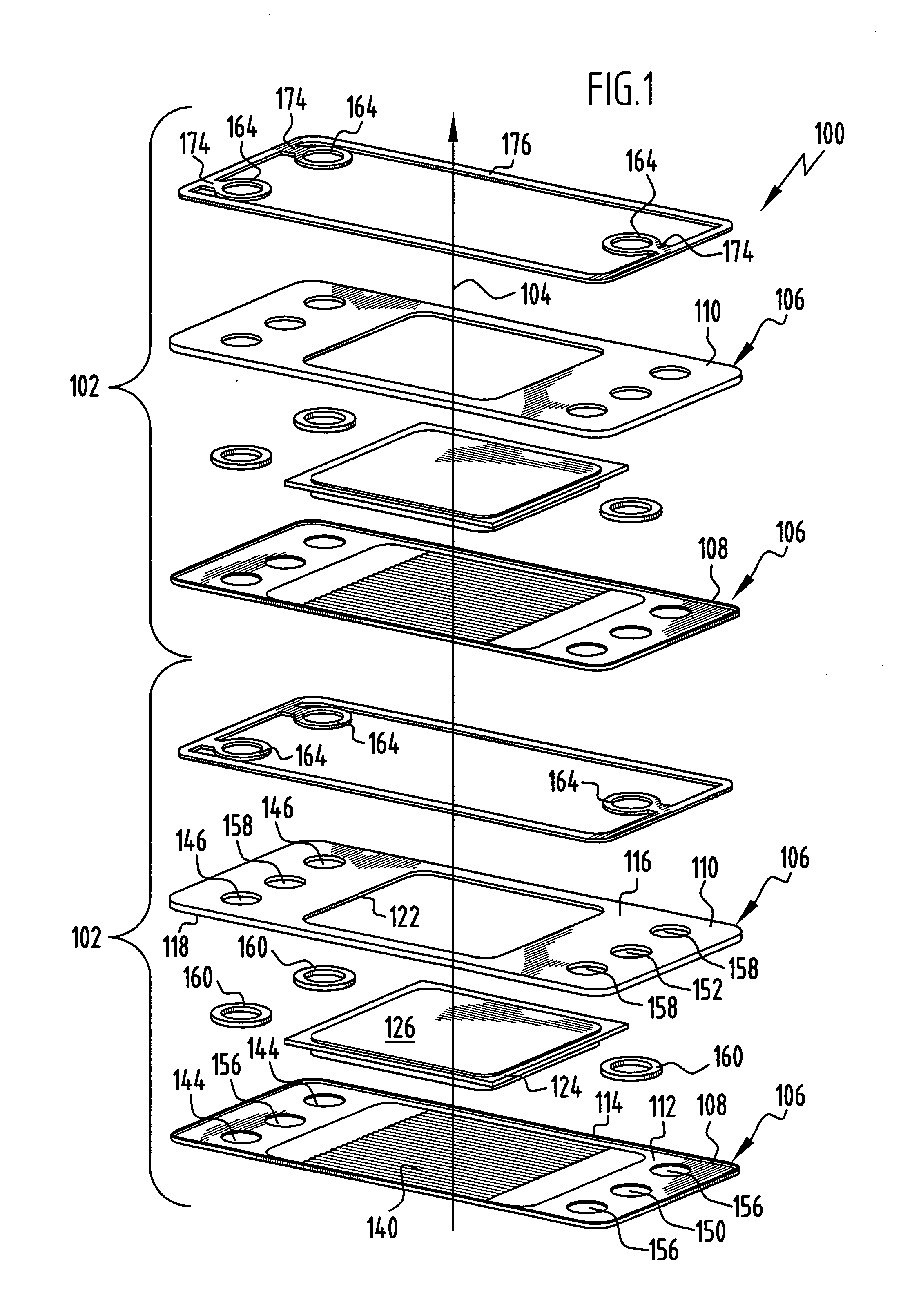
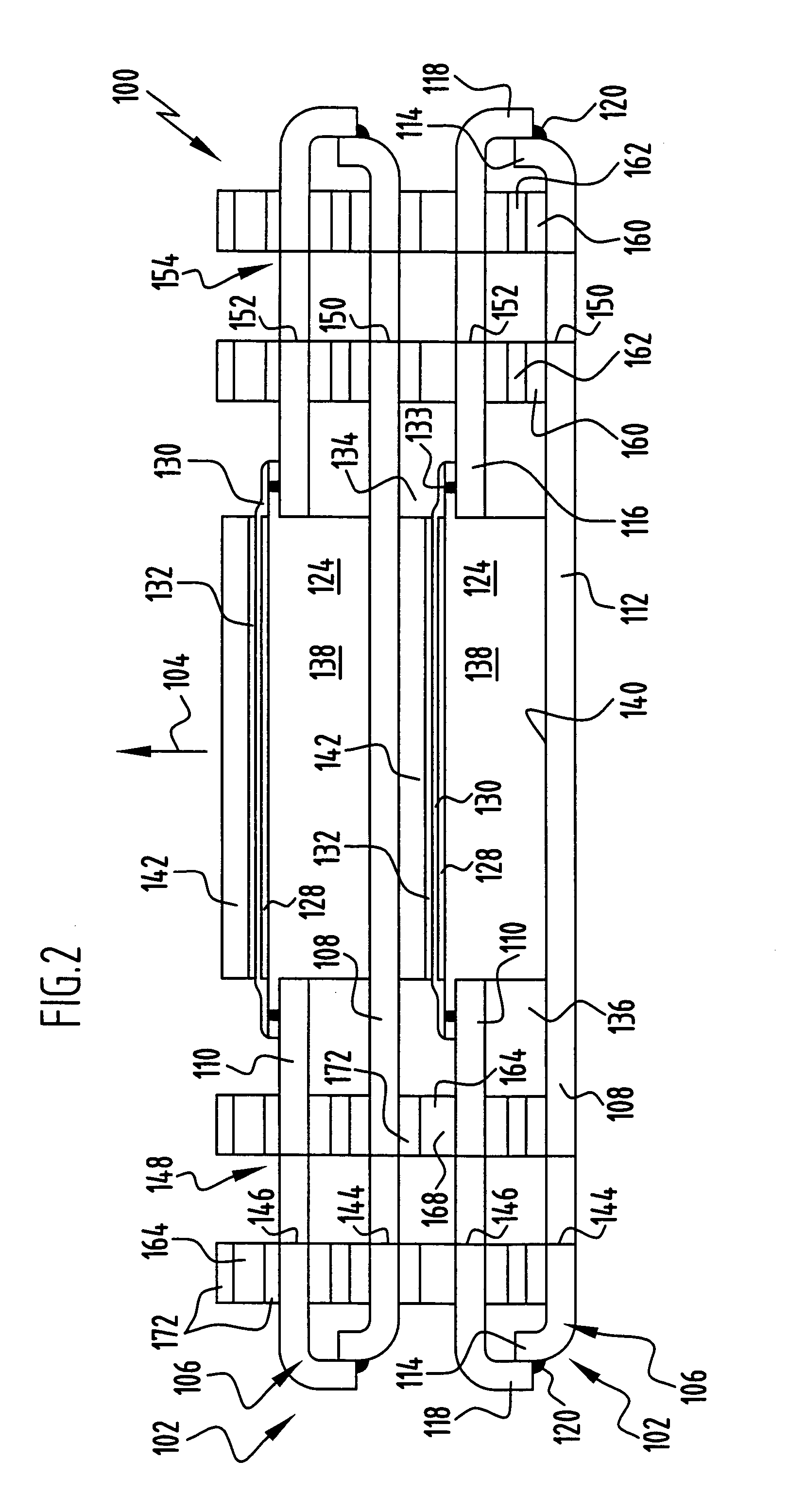
[0054] A fuel cell stack, which is illustrated in FIGS. 1 to 3 and denoted as a whole by 100, comprises a plurality of fuel cell units 102 each of an identical design, which are stacked one on top of the other along a vertical stacking direction 104.

[0055] Each of the fuel cell units 102 comprises a housing 106, which is composed of a housing lower part 108 and a housing upper part 110.

[0056] The housing lower part 108 takes the form of a shaped sheet-metal part and comprises a plate 112, which is aligned substantially at right angles to the stacking direction 104 and at its edges merges into a marginal flange 114, which is bent round substantially parallel to the stacking direction 104.

[0057] The housing upper part 110 likewise takes the form of a shaped sheet-metal part and comprises a plate 116, which is aligned substantially at right angles to the stacking direction 104 and at its edges merges into a marginal flange 118, which is bent round substantially parallel to the stack...


PUM

PropertyMeasurementUnit
temperatureaaaaaaaaaa
operating temperatureaaaaaaaaaa

Abstract

In order to provide a component of a fuel cell unit that has an electric insulation effect at the operating temperature of the fuel cell unit and that has an adequate electrically insulating effect and an adequate mechanical strength also at a high operating temperature of the fuel cell unit, it is proposed that the component comprises a basic body and at least one electrically insulating insulation layer, which is disposed on the basic body and contains aluminium oxide, wherein the insulation layer is produced by anodizing an aluminium-containing layer disposed on the basic body.

Description

[0001] The present disclosure refers to the subject matter disclosed in German patent application No. 103 58 458.7 of 13 Dec. 2003. The entire description of this earlier application is made a constituent part of the present description by reference (“incorporation by reference”). BACKGROUND OF THE INVENTION [0002] The present invention relates to a component of a fuel cell unit that has an electric insulation effect at the operating temperature of the fuel cell unit. [0003] Fuel cell units, for adjustment of the desired operating voltage, are disposed in the required number one on top of the other so as to obtain a fuel cell stack. In order to prevent an electric short circuit, the housings of successive fuel cell units in the fuel cell stack have to be electrically insulated from one another. [0004] In known fuel cell stacks, insulation elements made of glass solder or of ceramic sealing materials are used to achieve the required electric insulation effect. [0005] In the case of s...

Claims


Application Information

Patent Timeline
Patent Type & Authority Applications(United States)
IPC IPC(8): B23P19/00C25D3/66C25D9/00C25D11/00C25D11/04H01L27/10H01L29/73H01M2/00H01M2/02H01M2/08H01M2/14H01M8/02H01M8/10H01M8/24
CPCC25D11/04H01M8/0206H01M8/021Y10T29/53135H01M8/0282Y02E60/50H01M8/0228
Inventor SCHENK, PETERZERFASS, HANS-RAINER
Owner ELRINGKLINGER AG
Why Eureka
Try Eureka