Cabin pressure control method and apparatus using all-electric control without outflow valve position feedback

Active Publication Date: 2005-07-14
HONEYWELL INT INC
View PDF11 Cites 37 Cited by
  • Summary
  • Abstract
  • Description
  • Claims
  • Application Information

AI Technical Summary

Benefits of technology

[0009] The invention relates to a pressure control system for use with a pressurized aircraft cabin or other similar environment. In particular, and by way of example only, one embodiment of the invention is a pressure control system including an inflow unit, an outflow unit, a cabin pressure se

Problems solved by technology

There are many disturbances to the cabin pressurization such as the changing pressure distribution on the airframe due to ground, taxi, takeoff, landing, or flight maneuvers, or due to changing power in one or more engines that can be a source of pressurized air.
However, pneumatic and electro-pneumatic systems are mechanically complex in nature, and can often employ motorized bellows, solenoids, torque motors, springs, orifices, and micro valves to control the position of an outflow valve.
These systems require bleed air, or a vacuum source, and require tubing to be installed on the aircraft, making their installations more complex, costly, and less reliable.
Further, the pneumatic and electro-

Method used


Image

  • Cabin pressure control method and apparatus using all-electric control without outflow valve position feedback
  • Cabin pressure control method and apparatus using all-electric control without outflow valve position feedback
  • Cabin pressure control method and apparatus using all-electric control without outflow valve position feedback

Examples


Embodiment Construction

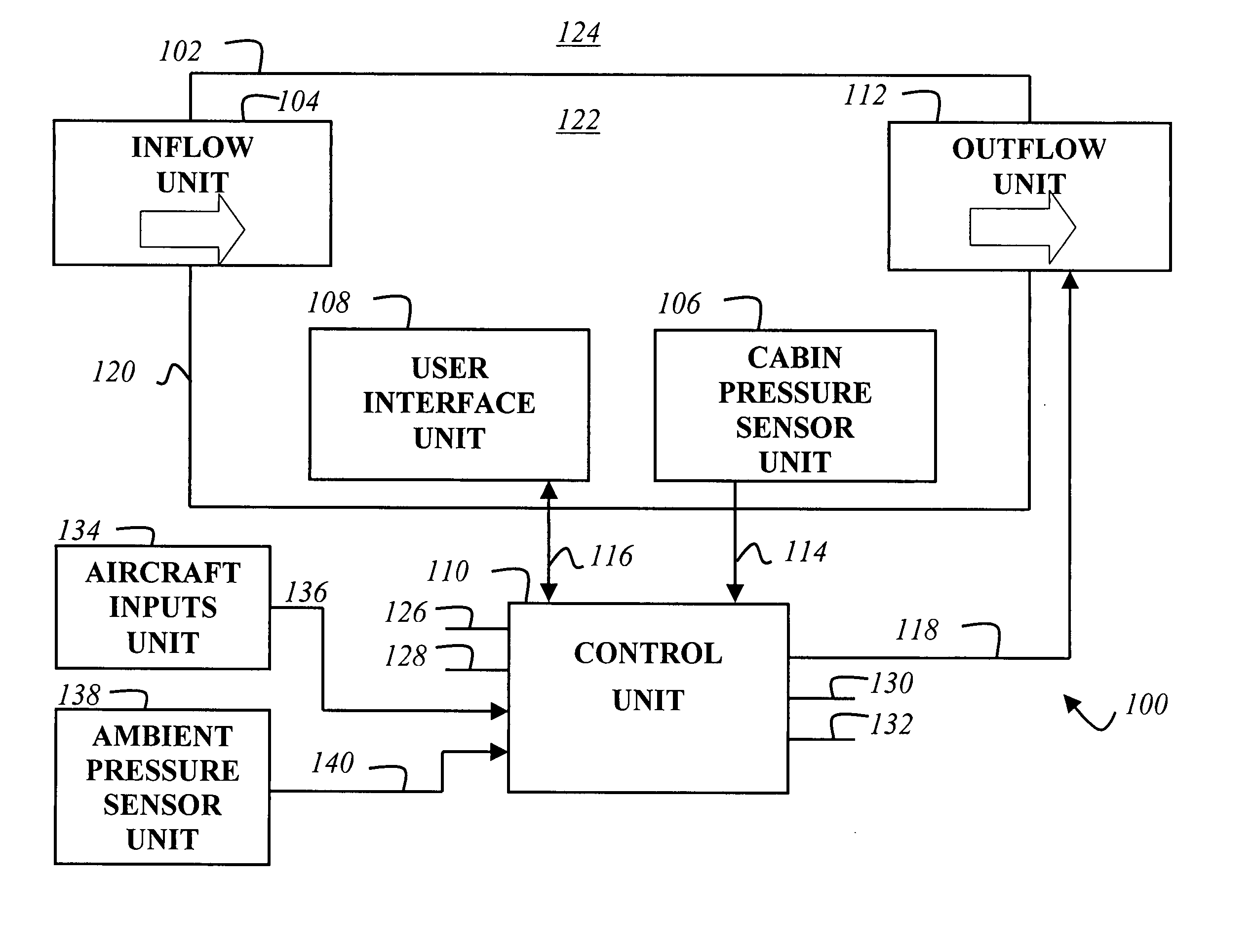
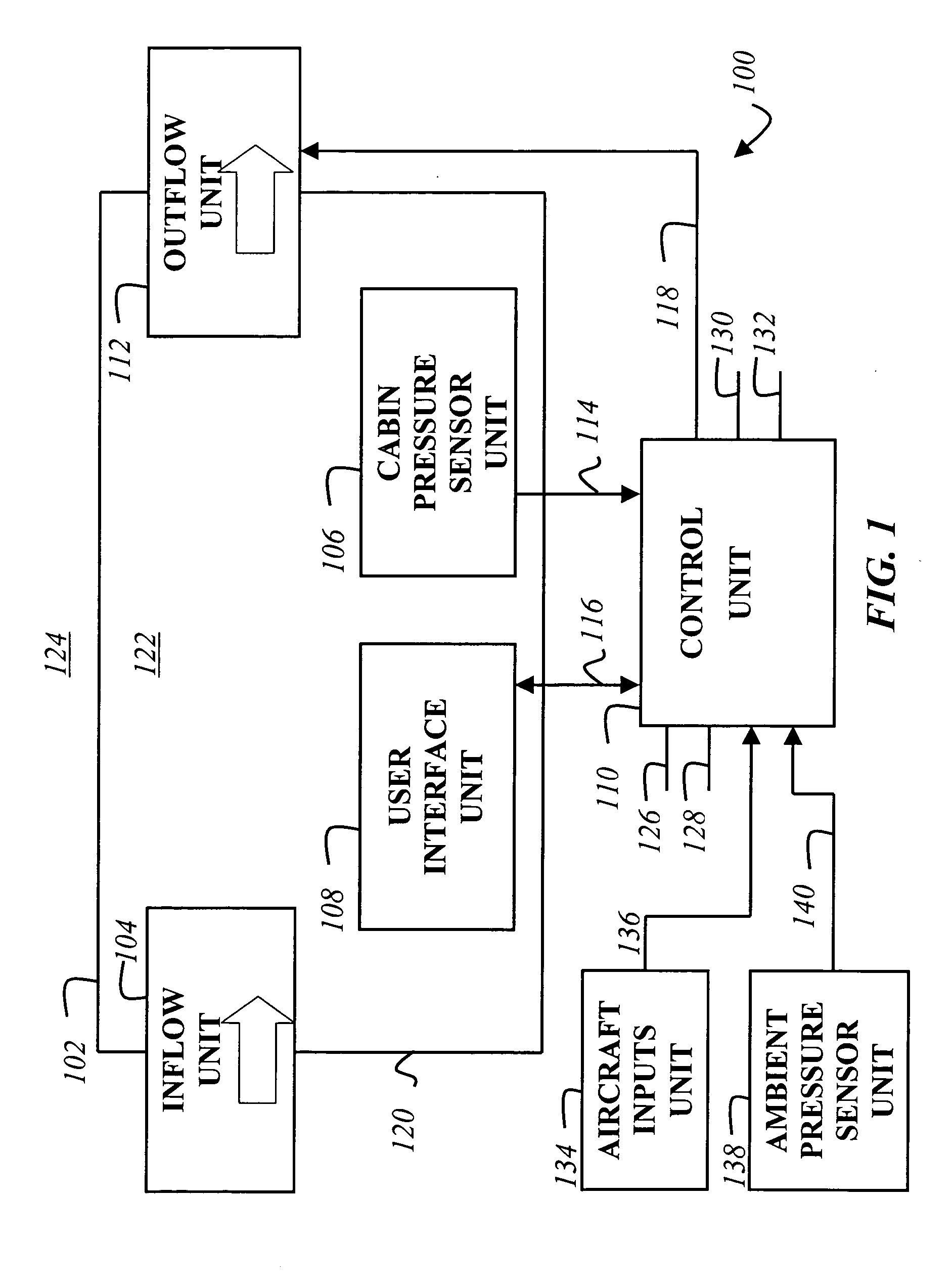
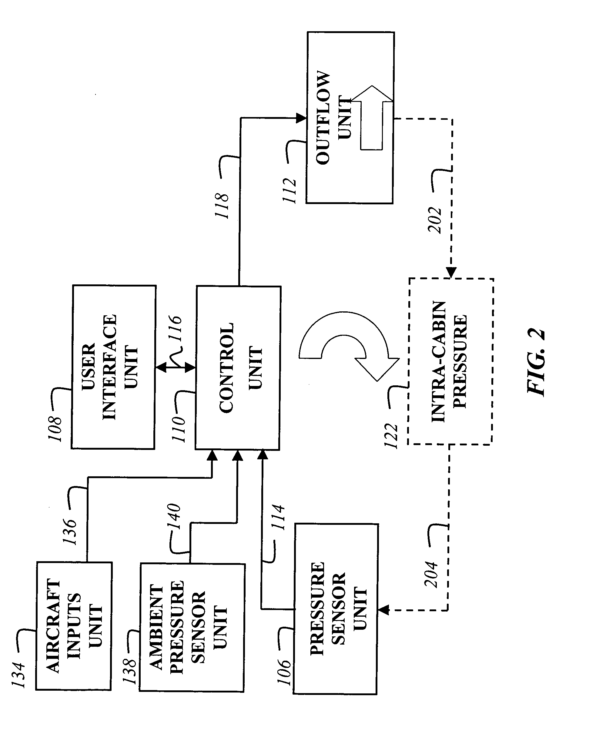
[0031] Systems and methods that implement the embodiments of the various features of the invention will now be described with reference to the drawings. The drawings and the associated descriptions are provided to illustrate embodiments of the invention and not to limit the scope of the invention. Reference in the specification to “one embodiment” or “an embodiment” is intended to indicate that a particular feature, structure, or characteristic described in connection with the embodiment is included in at least an embodiment of the invention. The appearances of the phrase “in one embodiment” in various places in the specification are not necessarily all referring to the same embodiment. Throughout the drawings, reference numbers are re-used to indicate correspondence between referenced elements. In addition, the first one or two digits of each reference number indicate the figure in which the element first appears, while the last two digits distinguish the element within the figure....


PUM


Abstract

A pressure control system including an inflow unit for admitting pressurized air into a cabin, an outflow unit including a motor for operating a valve to discharge air from the cabin at a predetermined rate based on an motor control signal that sets the motor speed, a control unit, and an air pressure sensor within the cabin for determining a pressure signal. The control unit receives the pressure signal and computes a pressure rate of change error signal to set the motor control signal. The outflow unit, control unit, and air pressure sensor form a feedback control loop independent of motor speed, valve speed, or valve position feedback.

Description

BACKGROUND OF THE INVENTION [0001] 1. Field of the Invention [0002] The present invention relates generally to pressure control systems for use in an aircraft environment, and more particularly to a cabin pressure control method and apparatus using all electric (electromechanical) control without outflow valve, motor speed, or position feedback. [0003] 2. Description of the Related Art [0004] Aircraft that fly at high altitudes require a pressurized cabin to allow occupants to safely travel without wearing an oxygen mask. The pressurized cabin is a dynamic environment impacted by the various conditions placed on the aircraft from before take-off to after landing. There are many disturbances to the cabin pressurization such as the changing pressure distribution on the airframe due to ground, taxi, takeoff, landing, or flight maneuvers, or due to changing power in one or more engines that can be a source of pressurized air. [0005] Cabin pressurization systems are of three basic archit...

Claims


Application Information

Patent Timeline
IPC IPC(8): B64D13/04G05D16/20
CPCG05D16/202B64D13/04
Inventor HORNER, DARRELL W.MCCOY, GERARD L.GALLAGHER, KENNETH M.BISS, TIMOTHY C.
Owner HONEYWELL INT INC
Why Eureka
Try Eureka