Image apparatus and method, and communication terminal device

a technology of communication terminal and image apparatus, which is applied in the direction of program control, testing/monitoring control system, instruments, etc., can solve the problems of difficult to be stolen by the third party, and the difficulty of practical use of the communication terminal device, and achieve the effect of simple us

Inactive Publication Date: 2005-07-14
SONY CORP
View PDF8 Cites 30 Cited by
  • Summary
  • Abstract
  • Description
  • Claims
  • Application Information

AI Technical Summary

Benefits of technology

[0013] This invention has been made in view of foregoing, and intends to propose an imaging apparatus which can be downsized and its method, and a communication terminal device capable of offering substantially simple use.

Problems solved by technology

As identification information, unique body features such as iris, finger prints of fingers or a palm are used, which are difficult to be stolen by the third party.
In addition, to install the blood vessel imaging function of the imaging apparatus 1 in a communication terminal device such as a portable telephone or a Personal Digital Assistant (PDA) to determine based on identification information which is obtained from the imaging apparatus 1 in communicating with the outside, whether the communication terminal device is being used by the third party, the communication terminal device is hard to be put into practical use due to the shielding unit 7.

Method used


Image

  • Image apparatus and method, and communication terminal device
  • Image apparatus and method, and communication terminal device
  • Image apparatus and method, and communication terminal device

Examples


first embodiment

(1) First Embodiment

(1-1) Construction of Imaging Apparatus

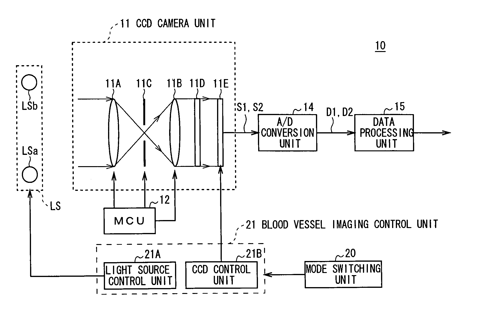
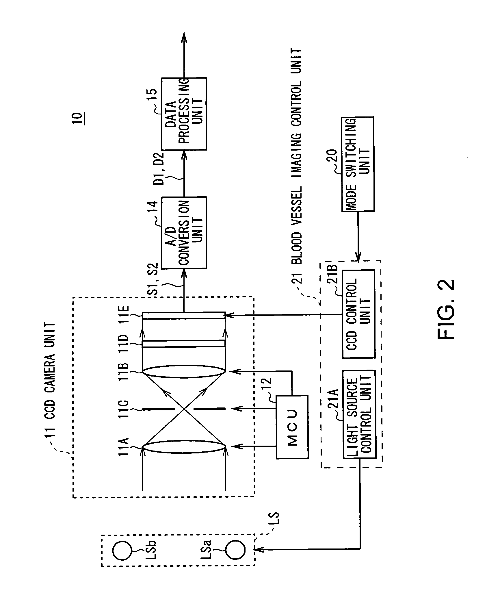
[0039]FIG. 2 shows an imaging apparatus 10 according to this embodiment. This imaging apparatus 10 executes a mode (hereinafter, referred to as normal imaging mode) to take pictures of subjects such as bodies and backgrounds as imaging targets.

[0040] In this case, a CCD camera unit 11 guides outside light in the air coming from a front subject, to a CCD 11E via a lens 11A, an aperture 11C, a lens 11B, and an ultraviolet cut filter 11D in order.

[0041] At this time, a Micro Control Unit (MCU) 12 adjusts the amount of the outside light entered into the CCD 11E by controlling the aperture 11C with an automatic exposure control process and also adjusts a focus distance and focus position by controlling the positions of the lens 11A and 11B with an auto focus control process.

[0042] This ultraviolet cut filter 11D comprises an RGB filter which has a pixel arrangement as shown in FIG. 3A and lets visible light and near-infrared...

second embodiment

(2) Second Embodiment

(2-1) External Construction of Portable Telephone

[0069]FIG. 7 shows an external construction of a portable telephone 50. Referring to this figure, this portable telephone 50 has a thin rectangular solid case 51, and is provided with a display unit 52, an operating part 53 composed of a plurality of operating buttons, a loudspeaker 54, and a microphone 51B on its front side 51A. On the back side 51B, on the other hand, a telescopic antenna 56 and a removable power battery 57 are provided.

[0070] Further, referring to FIG. 8A, this portable telephone 50 is provided with a CCD camera unit 11, for example, on the back side 51B to take pictures of normal subjects such as people and scenery.

[0071] In addition to the above units, in this portable telephone 50, near-infrared light sources LS (LSa and LSb) for irradiating the arrival direction side of outside light with near-infrared light are arranged on the same plane as the arrangement position of the CCD camera un...


PUM


Abstract

To realize downsizing. This invention provides an imaging apparatus with an irradiation means for irradiating a body with irradiation light stronger than light in the air coming to the body, a solid imaging element for performing photoelectric conversion on a pattern light of unique tissues obtained through the body, and a sensitivity adjustment means for adjusting the imaging sensitivity of the solid imaging element to the unique tissues by limiting the amount of a signal which is stored per unit time through the photoelectric conversion in the solid imaging element.

Description

BACKGROUND OF THE INVENTION [0001] 1. Field of the Invention [0002] This invention relates to an imaging apparatus and method, and a communication terminal device and, more particularly, is suitably applied to a case of creating information (hereinafter, referred to as identification information) certifying the validly of an identification target, for example. [0003] 2. Description of the Related Art [0004] As identification information, unique body features such as iris, finger prints of fingers or a palm are used, which are difficult to be stolen by the third party. [0005] Recently, a blood vessel formation pattern inside a body has been a focus of attention as one of such unique body features. Then an identification apparatus has been proposed to create the blood vessel formation pattern as identification information by using such a feature that deoxygenization hemoglobin (venous blood) or oxygenization hemoglobin (arterial blood) in blood vessels specifically absorb light (near-...

Claims


Application Information

Patent Timeline
Patent Type & Authority Applications(United States)
IPC IPC(8): A61B5/00A61B5/117H04M1/66A61B5/145G06T1/00G06V40/145H04M1/00H04M1/02
CPCA61B5/0059A61B5/117A61B5/0013A61B5/6838G06K9/00013A61B5/6826A61B5/1171G06V40/145H04M1/66
Inventor SATO, HIDEO
Owner SONY CORP
Why Eureka
Try Eureka