Needleless injector with shock absorbing means between ram and piston

a technology of shock absorption and injector, which is applied in the direction of medical syringes, automatic syringes, intravenous devices, etc., can solve the problems of incomplete injection and high localised stress, and achieve the effect of reducing the initial transfer force and reducing the initial pressure increase on the liquid

Inactive Publication Date: 2005-07-14
ZOGENIX INC
View PDF27 Cites 6 Cited by
  • Summary
  • Abstract
  • Description
  • Claims
  • Application Information

AI Technical Summary

Benefits of technology

[0013] shock absorbing means for reducing an initial transfer of force from the ram to the piston.
[0014] This apparatus provides reduction of the initial force applied to the ram, so that the initial rate of pressure increase on the liquid is reduced, thereby controlling the rate of collapse of gas bubbles in the liquid.

Problems solved by technology

This bubble collapse, if it occurs quickly enough, can cause shock waves within the capsule, which can give rise to extremely high localised stresses.
These stresses can sometimes cause the capsule to fail during this initial pressure peak, which is likely to result in an incomplete injection.

Method used


Image

  • Needleless injector with shock absorbing means between ram and piston
  • Needleless injector with shock absorbing means between ram and piston
  • Needleless injector with shock absorbing means between ram and piston

Examples


Embodiment Construction

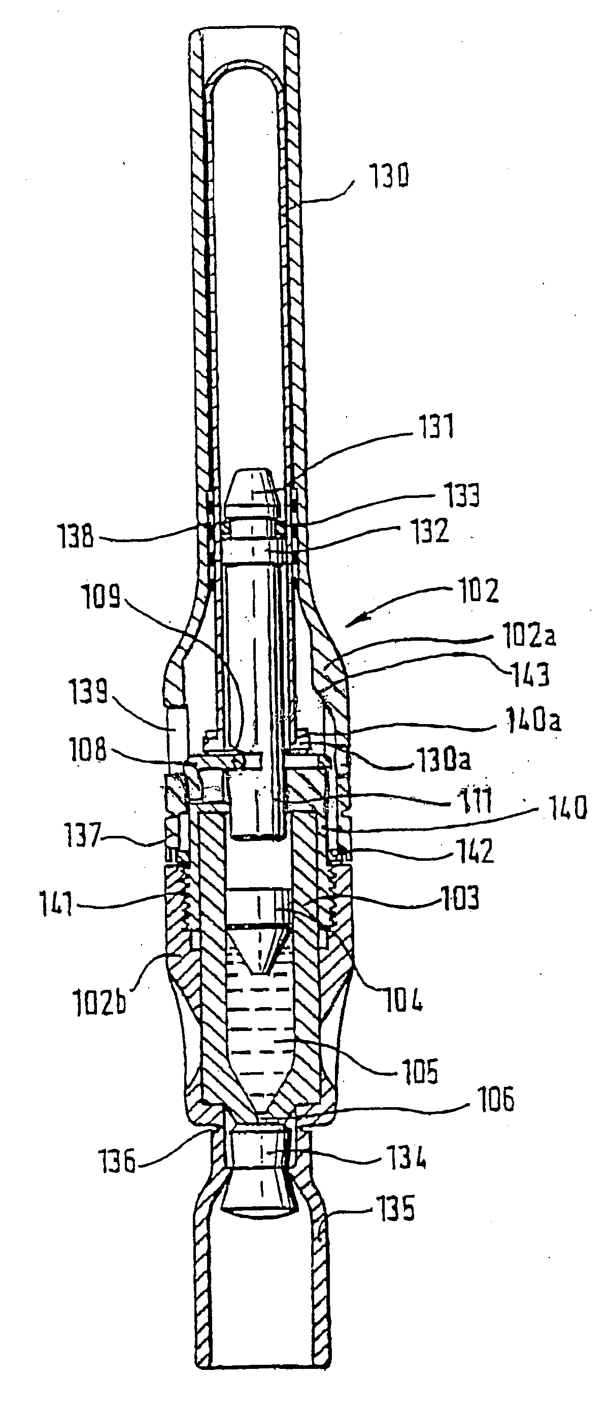
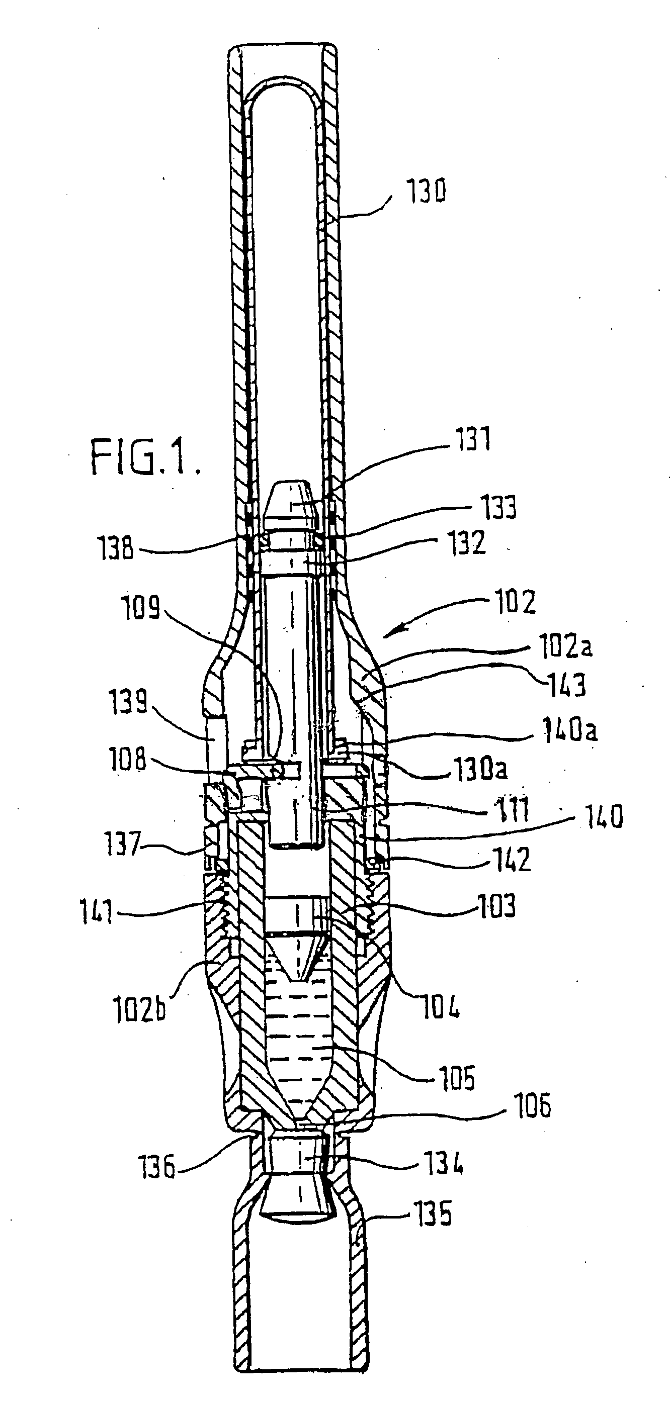
[0035]FIG. 1 shows a known needleless injector, comprising a syringe body in the form of a cartridge 103 having an opening 106 at one end. A piston 104 is housed within the cartridge 103 for urging a liquid 105 within the cartridge through the opening 106. A ram 111 is provided for driving the piston, and an arrangement is provided for applying a force to the ram 111.

[0036] The are numerous possible ways of applying force to the ram. In the example shown, the injection force is provided by a compressed gas spring. This is in the form of a cylinder 130 which is closed at its upper end and which contains gas, typically air, under a pressure which is typically in the range 5.5 MPa (800 psi) to 22 MPa (3000 psi). The cylinder houses the ram 111. The end of the ram 111 has a frustoconical portion 131 and a flange 132 between which is situated an O-ring seal 133. Prior to use, the ram 111 is held in the illustrated position by a latch 108 engaging in a groove in the ram, the upper surfac...


PUM


Abstract

A needleless injector has a syringe body having an opening at one end, a piston housed within the syringe body for urging a liquid within the syringe body through the opening and a ram for driving the piston. A shock absorbing component is provided for reducing an initial transfer of force from the ram to the piston. The initial rate of pressure increase on the liquid is reduced, thereby controlling the rate of collapse of gas bubbles in the liquid.

Description

BACKGROUND TO THE INVENTION [0001] Needlefree injectors are used as an alternative to needle-type hypodermic injectors for injecting liquid drugs through the epidermis and into the underlying tissues. The usual form of construction for such a device is a syringe having a small discharge orifice which is placed in contact with the skin, and through which the drug is injected at a sufficiently high speed to penetrate the skin of the patient. The energy required to pressurise the drug may be derived from a compressed coil spring, compressed gas, explosive charge or some other form of stored energy. [0002] There are a number of different ways in which the energy may be converted from the stored form into pressure in the liquid. These may include rupturing a seal, so allowing gas to escape from a canister and causing pressure to build up behind a piston which pressurises the gas. Alternatively, a gas may cause a ram to accelerate across a gap, prior to impacting on the back of a piston. ...

Claims


Application Information

Patent Timeline
Patent Type & Authority Applications(United States)
IPC IPC(8): A61M5/30A61M5/31
CPCA61M5/30A61M2005/2073A61M5/3159A61M2005/312A61M5/31511A61M2005/2086
Inventor GREEN, TERRY
Owner ZOGENIX INC
Why Eureka
Try Eureka