Stent reducing system and device

a stent and stent technology, applied in the direction of prosthesis, forging/pressing/hammering apparatus, blood vessels, etc., can solve the problems of stent removal, excessive force is often required to remove the stent, and the stent is not loaded successfully, so as to minimize or eliminate direct contact, reduce friction between the blade and the stent, and minimize the adherence of the stent

Active Publication Date: 2005-07-14
BOSTON SCI SCIMED INC
View PDF33 Cites 77 Cited by
  • Summary
  • Abstract
  • Description
  • Claims
  • Application Information

AI Technical Summary

Benefits of technology

[0019] The present invention is embodied in a variety of forms. In at least one embodiment the invention is directed to a stent reducing and/or loading mechanisms such as stent crimpers and associated reducing and loading tools. In some embodiments a crimper comprises a contractible opening or stent reduction chamber defined by two or more members which define the opening. In at least one embodiment the chamber is an iris or other contractible and expandable opening defined by a plurality of moveable contacting members or blades. The chamber has a variable diameter and may be adjusted between an open diameter and a closed di

Problems solved by technology

It can also affect the dilatation length of the stent and lead to pinching of the balloon.
If the force exerted on the stent by the mandrel is greater than the column strength of the stent the stent will buckle thereby leading to an unsuccessful loading of the stent.
Unfortunately, such excessive force is often required to remove the stent from the crimper.
In addition to potentially buckling the stent, the force exerted by direct contact of the crimper blades on the stent as well as t

Method used


Image

  • Stent reducing system and device
  • Stent reducing system and device
  • Stent reducing system and device

Examples


Embodiment Construction

[0042] As is depicted in the various FIGS. 1-12, the present invention comprises embodiments which address the shortcomings described above.

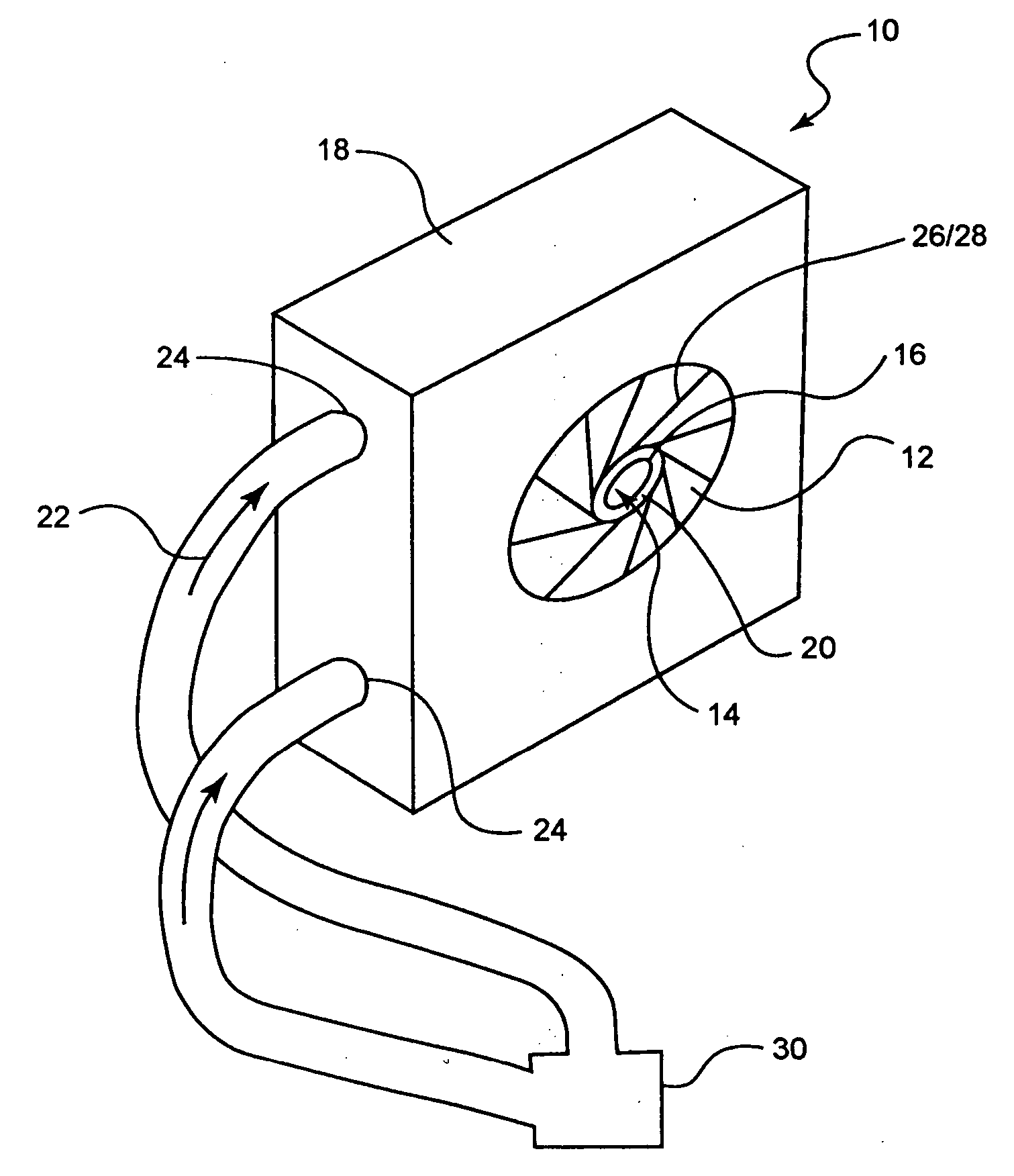
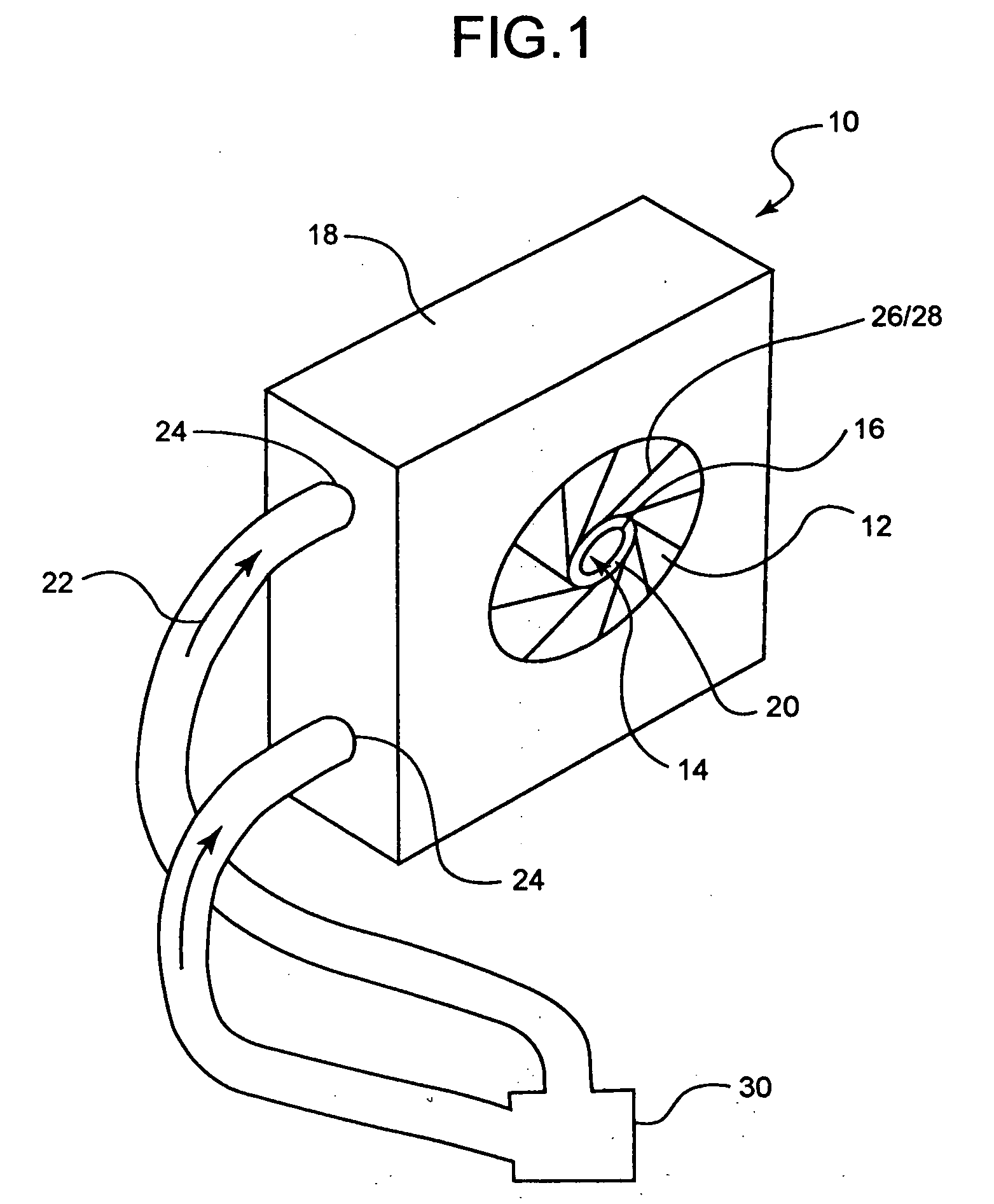
[0043] As indicated above, the present invention is embodied in a variety of forms. In at least one embodiment, such as for example in the embodiment depicted in FIG. 1, the invention is directed to a radial stent reducing assembly or crimper 10. Crimper 10 may have any configuration of contacting members and / or any configuration of stent diameter reducing chamber, such as has been described above.

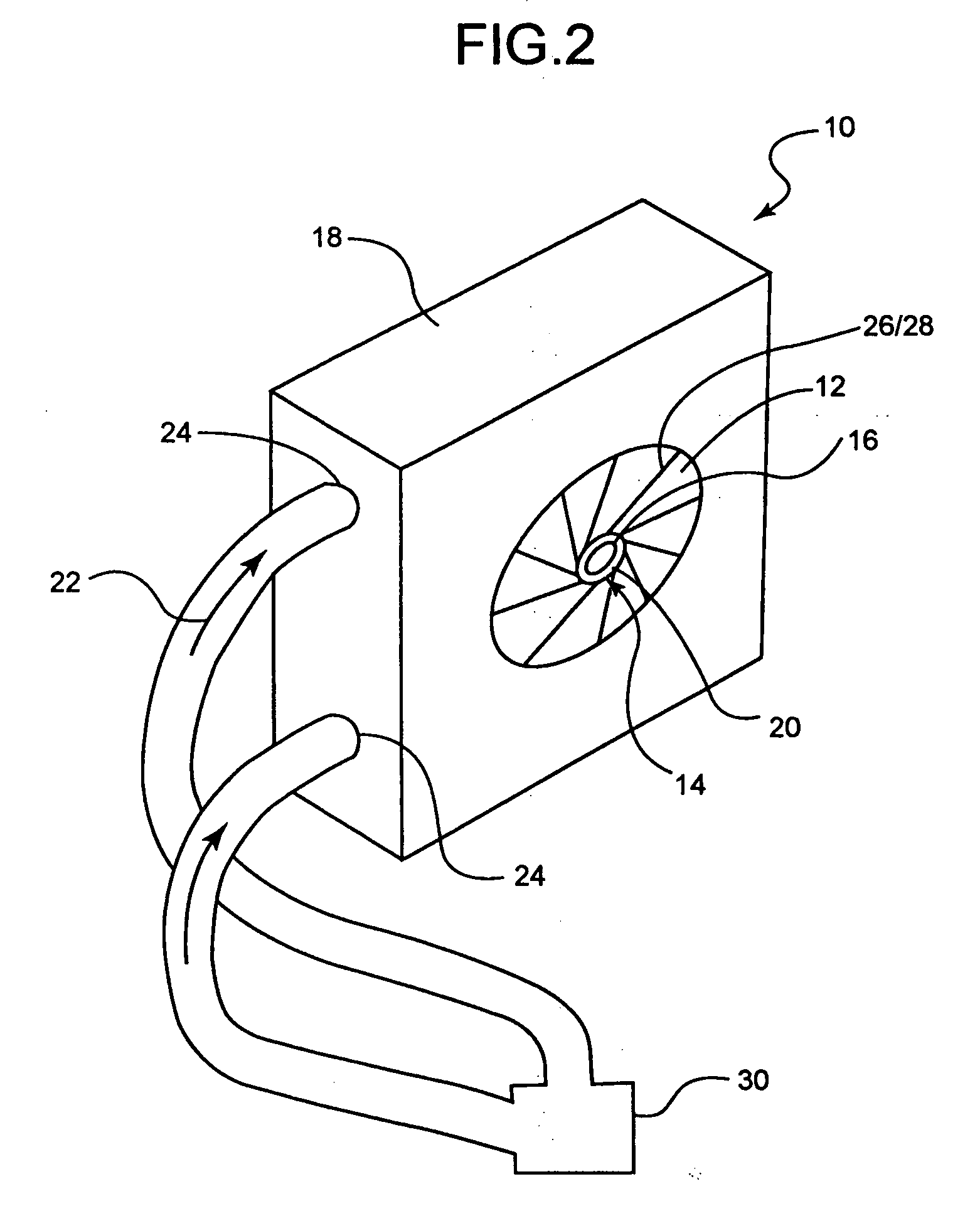
[0044] In the embodiment shown, crimper 10 is provided with a plurality of stent reducing members or blades 12 which define a stent reduction chamber 14 into which a stent or other medical device 16 is positioned in order to reduce the stent 16 from an unreduced diameter state, such as is shown in FIG. 1 to a reduced diameter state as is shown in FIG. 2. Unlike many prior stent crimping devices, the crimper 10 in the embodiment shown in FIGS. 1-3 is ...


PUM

PropertyMeasurementUnit
Temperatureaaaaaaaaaa
Diameteraaaaaaaaaa
Therapeuticaaaaaaaaaa

Abstract

A system for reducing the diameter of a stent comprises a stent contracting assembly and a fluid source. The assembly comprises a plurality of contracting members that define a diameter reduction chamber for receiving a stent. When the chamber is in a pre-reduction configuration the stent has a first diameter and when the chamber is in a reduced configuration the stent has a second diameter. The second diameter is less than the first diameter. The fluid source is in fluid communication with the chamber and is constructed and arranged to inject a fluid therein. The fluid forms a fluid bearing between the contracting members and the stent which prevents the contracting members from contacting the stent in the reduced diameter configuration.

Description

CROSS-REFERENCE TO RELATED APPLICATIONS [0001] Not Applicable STATEMENT REGARDING FEDERALLY SPONSORED RESEARCH [0002] Not Applicable BACKGROUND OF THE INVENTION [0003] 1. Field of the Invention [0004] The present invention relates generally to stents, stent loading, stent contracting and stent delivery systems and their respective methods of use. Some embodiments of the invention are more specifically directed to stent loading and crimping systems which are configured for reduced frictional interface between a stent and one or more system component which contact the stent during the crimping and loading process. [0005] 2. Description of Related Art [0006] A stent is a generally tubular device that is used to support a bodily lumen. A stent is typically delivered to a desired bodily location via a catheter. Often the stent is loaded onto a portion of the catheter, such as a balloon or other region of the catheter shaft. In some stent delivery systems the stent is crimped to the cathe...

Claims


Application Information

Patent Timeline
IPC IPC(8): A61F2/06A61F2/84
CPCA61F2002/9522A61F2/95A61F2/9522A61F2/9524
Inventor LARSON, KARENJAGGER, KARL A.GUNDERSON, RICHARD C.GERDTS, MICHAEL
Owner BOSTON SCI SCIMED INC
Why Eureka
Try Eureka