Failure diagnostic apparatus for variable valve mechanism of internal combustion engine and failure diagnostic method for variable valve mechanism

a technology of failure diagnostic apparatus and internal combustion engine, which is applied in the direction of valve drives, process and machine control, instruments, etc., can solve the problems of internal combustion engine stoppage, inability to adjust the working angle of the valve, and decrease in the intake air amount, so as to increase the reliability of refuge running and reduce the level of performance

Inactive Publication Date: 2005-07-14
TOYOTA JIDOSHA KK
View PDF3 Cites 18 Cited by
  • Summary
  • Abstract
  • Description
  • Claims
  • Application Information

AI Technical Summary

Benefits of technology

[0008] It is an object of the invention to increase reliability of refuge running when a failure has occurred in a variable valve mechanism. The term “refuge running” as used herein is defined to mean running of a vehicle at a reduced level of performance due to a failure in the vehicle, which will allow the driver to drive the vehicle to a safe place or a service garage for repair.
[0011] In the maintaining control, the valve characteristic value is maintained at a value in the refuge running performable region. As mentioned above, the failure diagnosis is performed when the valve characteristic value is at a value in the refuge running performable region. Accordingly, when the valve characteristic value is maintained at a value in the refuge running performable region in the maintaining control, the valve characteristic value need not be adjusted and is maintained as it is. It is therefore possible to perform the maintaining control even when a failure has occurred in the variable valve mechanism.
[0013] According to this failure diagnostic method, when it is determined that a failure has occurred in the variable valve mechanism, it is possible to maintain the valve characteristic value at a value in the refuge running performable region.

Problems solved by technology

However, when a failure occurs in the actuator or the sensor, the valve working angle cannot be adjusted.
As a result, in some cases, the internal combustion engine stops due to a decrease in the intake air amount and refuge running cannot be performed.
Therefore, when a failure in the sensor is detected, the internal combustion engine needs to be operating actually.
Accordingly, there is a high possibility that it will become difficult to start the internal combustion engine or to operate the internal combustion engine continuously and stably, making it impossible to perform the refuge running.
Further, if a failure has occurred in the actuator instead of in the sensor and the valve working angle cannot be changed, it becomes impossible to increase an output of the engine by increasing the valve working angle and to perform the refuge running.
However, when a failure has occurred in the actuator, it becomes impossible to resist this force.
Therefore, the internal combustion engine is stopped, afterwhich it is impossible to start the internal combustion engine and perform the refuge running.

Method used


Image

  • Failure diagnostic apparatus for variable valve mechanism of internal combustion engine and failure diagnostic method for variable valve mechanism
  • Failure diagnostic apparatus for variable valve mechanism of internal combustion engine and failure diagnostic method for variable valve mechanism
  • Failure diagnostic apparatus for variable valve mechanism of internal combustion engine and failure diagnostic method for variable valve mechanism

Examples


first embodiment

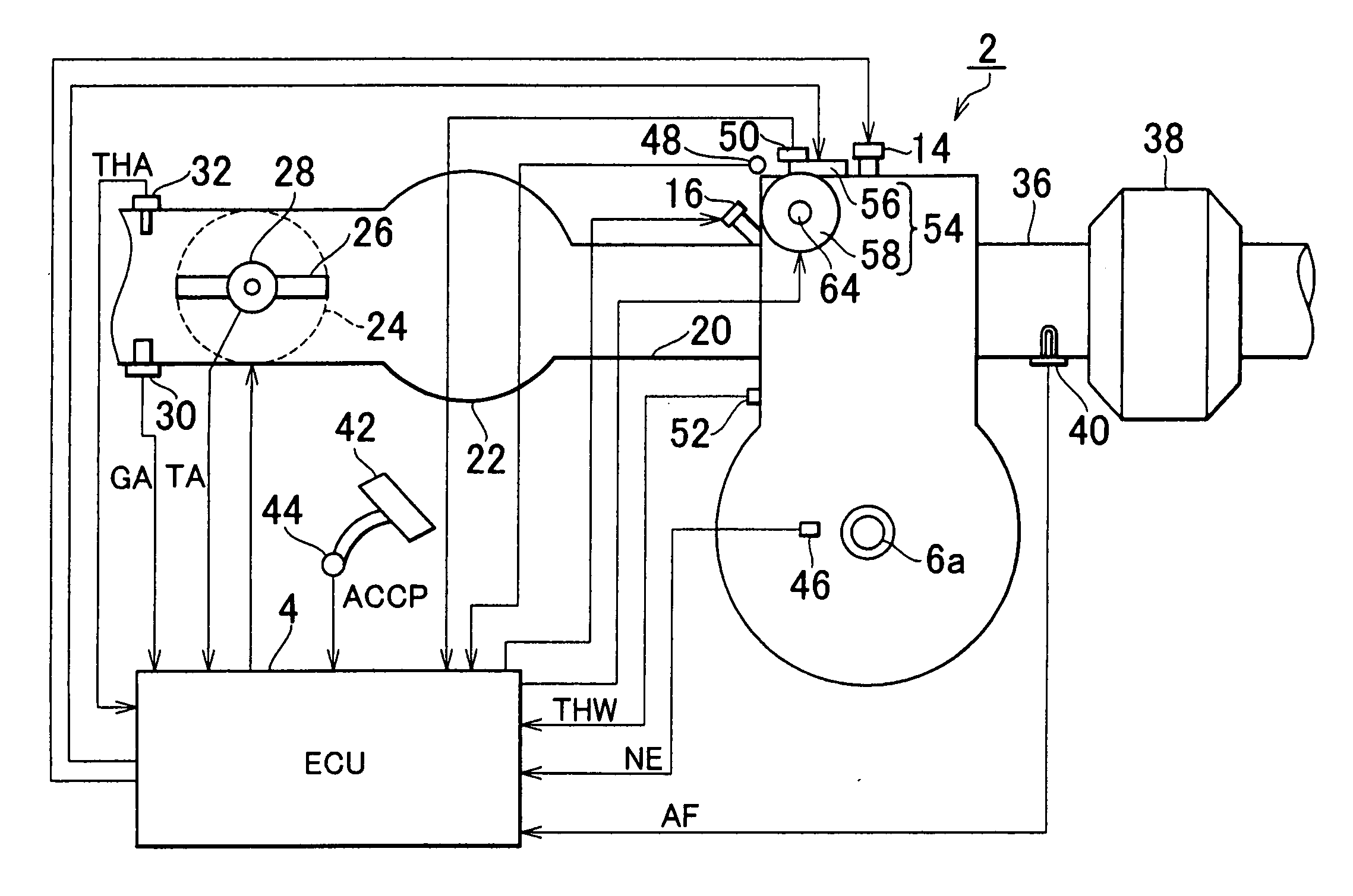
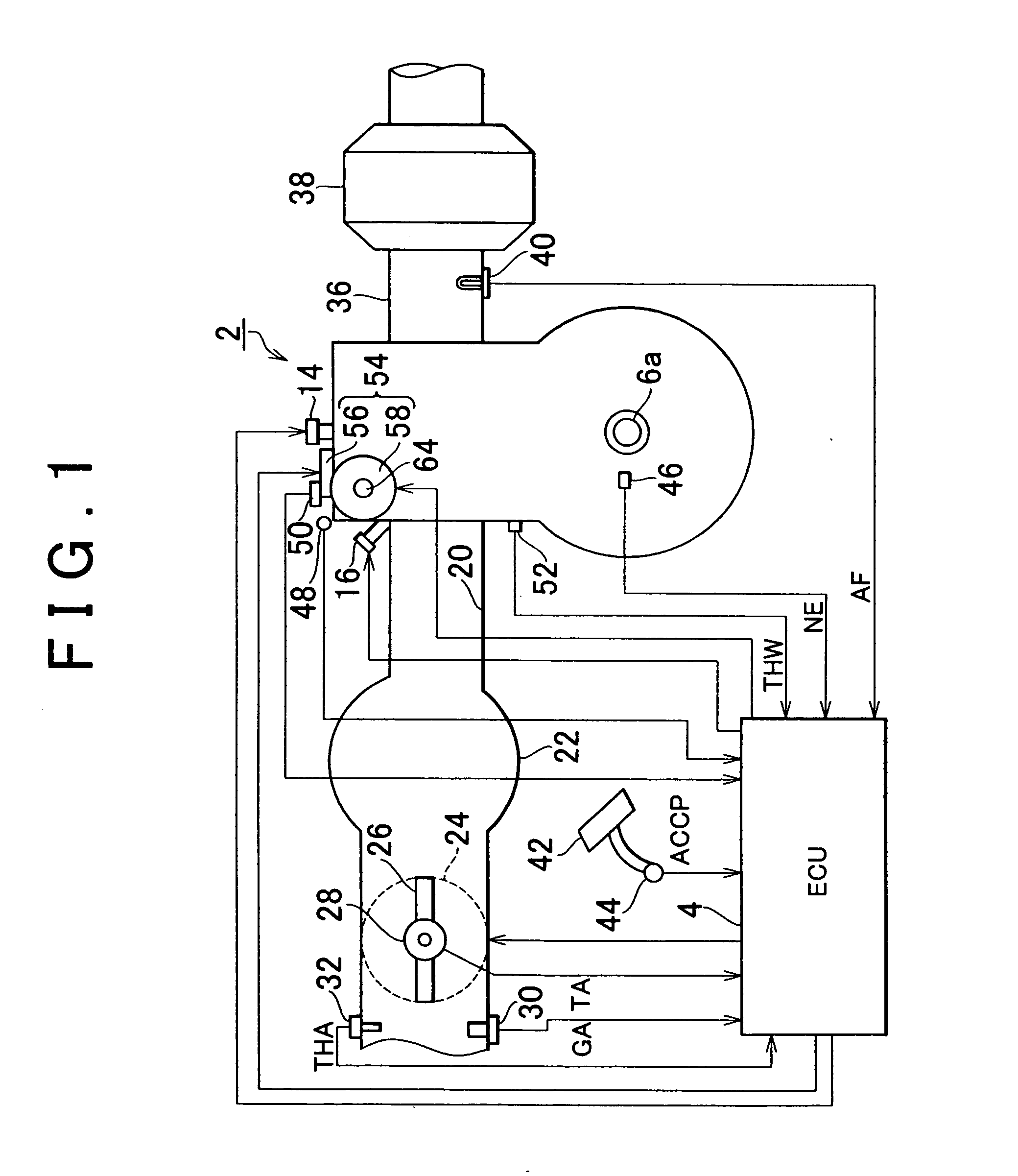
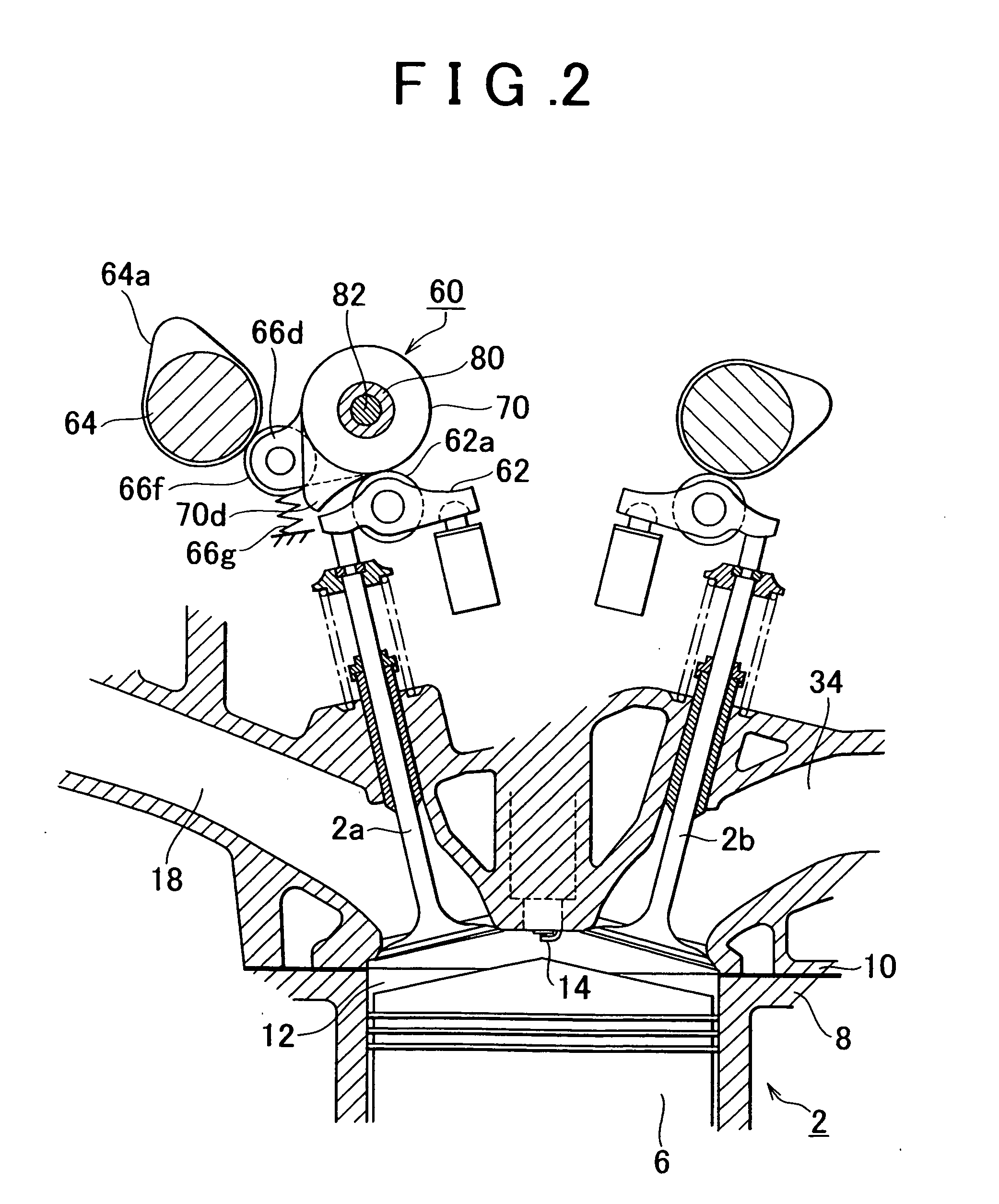
[0037] Hereafter, the invention will be described in detail with reference to accompanying drawings. FIG. 1 is a view schematically showing a structure of a gasoline engine (hereinafter, simply referred to as an “engine”) 2 as an internal combustion engine mounted in a vehicle and an electronic control unit (hereinafter, simply referred to as an “ECU”) 4 as a control unit. The engine 2 is a multi-cylinder engine, that is, a four-cylinder engine in the embodiment. FIG. 2 is a longitudinal section view showing a variable valve system of one cylinder from among the four cylinders. Each cylinder is provided with two intake valves 2a and two exhaust valves 2b, and the engine is formed as a four-valve engine. Note that the number of cylinders may be six or eight, and the engine may be a two-valve engine or a five-valve engine.

[0038] An output from the engine 2 is transferred to a wheel via a transmission as a driving force for running. In the engine 2, a combustion chamber 12, which is su...

second embodiment

[0127] described so far, the following effects can be also obtained.

[0128] (A) The effects in the descriptions (A) to (C) in the first embodiment can be also obtained in the case where a failure has occurred in the drive motor 102.

[0129] (B) Driving of the drive motor 102 for the failure diagnosis is performed at an output at a level lower than the output of a driving force in the normal state. Therefore, even when a collision with the stopper occurs, the amount of movement at the time of collision is small. It is therefore possible to increase durability of the valve working angle adjusting mechanism 56, and prevent a sense of discomfort due to an impulsive sound, which is felt by a driver.

[0130] (C) In the failure diagnosis, first, the drive motor 102 is driven such that the valve working angle is increased. When a failure has occurred in the drive motor 102 in the operation for increasing the valve working angle, the maintaining control is immediately performed. Then, the valv...

third embodiment

[0153] described so far, the following effects can be obtained.

[0154] (A) The effects in the descriptions (A) to (C) in the first embodiment can be obtained also in the third embodiment, although the third embodiment differs from the first embodiment in that the worm gear 304 is used in the shaft slide mechanism 300 and the valve working angle is not the maximum value in the refuge running performable region in the third embodiment.

[0155] The torque is generated by the drive motor 302 such that the valve working angle is increased in order to suppress vibration during the operation of the engine. In this case as well, the driving force output from the drive motor 302 may be smaller than that of in the normal state. Accordingly, only a small amount of energy is required to generate the torque. In addition, since this small amount of output does not move the control shaft 82, the internal member of the variable valve mechanism 54 and the control shaft 82 are prevented from colliding...


PUM


Abstract

A failure diagnosis for a slide sensor of a variable valve mechanism is performed when a valve working angle is at a value in the initial state. The initial state is set to a valve characteristic state where the valve working angle is at the maximum value. The maximum valve working angle corresponds to the refuge running performable region in which an engine can be started and refuge running can be performed. Therefore, even when it is difficult to adjust the valve working angle using rotation of a spiral cam due to a failure in the slide sensor, the refuge running can be performed only by maintaining the initial state by maintaining control. It is thus possible to increase reliability of the refuge running in the case where a failure has occurred in the variable valve mechanism.

Description

INCORPORATION BY REFERENCE [0001] The disclosure of Japanese Patent Application No. 2004-007132 filed on Jan. 14, 2004, including the specification, drawings and abstract is incorporated herein by reference in its entirety. BACKGROUND OF THE INVENTION [0002] 1. Field of the Invention [0003] The invention relates to a failure diagnostic apparatus for a variable valve mechanism which detects a valve characteristic value of an internal combustion engine by using a sensor, and which adjusts the valve characteristic value based on the detected valve characteristic value, and a failure diagnostic method for the variable valve mechanism. [0004] 2. Description of the Related Art [0005] There is a known variable valve mechanism which adjusts an intake air amount by changing a valve working angle in order to improve fuel efficiency in an internal combustion engine. In such a variable valve mechanism, there are provided an actuator for driving the mechanism and a sensor for detecting an adjust...

Claims


Application Information

Patent Timeline
Patent Type & Authority Applications(United States)
IPC IPC(8): F01L3/24F01L1/04F01L13/00F02D13/02G06G7/70
CPCF01L1/185F01L13/0005F01L13/0063F01L2105/00F01L2820/042F01L2800/01F01L2800/12F01L2820/033F01L2820/041F01L2800/00F01L2305/00
Inventor FUWA, NAOHIDEMUTO, HARUFUMI
Owner TOYOTA JIDOSHA KK
Why Eureka
Try Eureka